


Recent progress in Green Ammonia: Production, applications, assessment; barriers, and its role in achieving the sustainable development goals
Fossil fuels are no longer accepted as the sole energy source with their environmental impacts and fluctuating price. Green hydrogen is considered a potential candidate for fossil fuel soon—however, hydrogen is facing the challenges of storage and transportation. Green ammonia, with its ease of transport and storage, is another promising alternative. Decarbonizing ammonia production is an environmental press toward achieving net-zero emissions by 2050. This work summarizes the up-to-date progress in the green ammonia production methods. An assessment of the different production methods was conducted to highlight the merits and constraints of each approach. Moreover, the promising applications of green ammonia in the energy sectors were discussed. The various barriers, i.e., technical, economic, environmental, and regulations and policies, facing the widespread of green ammonia were also discussed. Finally, the contribution of green ammonia in achieving the different sustainable development goals was elaborated, focusing on the contribution of green ammonia in achieving climate change (SDG 13), clean energy (SDG 7), and other sustainability-related goals. Low efficiencies, high cost, and negative environmental impacts are the common challenges of the various production methods. The progress in green ammonia is essential for achieving SDG2, “Zero hunger”. SDG3 “healthy life and well-being” and SDG13 “Climate action”, will be achieved by eliminating 3.85 kg CO2-eq/kg NH3 emitted from conventional ammonia-based processes. Ease storing of green ammonia in liquid form (at 9 bar or cooling to −33°); makes it the best green energy source, i.e., achieving SDG7 “green and affordable energy”. By 2050, green ammonia is expected to represent 99 % of marine fuel, thus contributing to SDG9 “Industry and Infrastructure”. Moreover, green ammonia production will save 35.2 GJ of natural gas, thus achieving SDG12 “Responsible consumption/production”.
1. Introduction
Rapid use of fossil fuels has led to serious health problems and considerable climate change [1]. The widespread use of renewable energy sources is considered the best available route for controlling climate change and its associated problems [2]. Renewable energy sources are sustainable with minimal or no environmental impact [3]. The most common renewable energy sources, wind and solar, are intermittent and have varying intensities. Employing energy storage systems is considered a valid option to optimize and sustain renewable energy supply, such as thermal energy storage [4], [5], mechanical energy storage systems [6], [7], electrochemical energy storage systems [8], [9], or chemical energy storage systems [10], [11]. Green hydrogen integrated with renewable energy systems is one of the good choices for achieving this purpose [12], [13]. However, the difficulties of hydrogen storage and transport limit its application [14]. Hydrogen energy carriers such as methanol, ammonia, hydrazine, etc., can be applied to overcome the abovementioned challenges. Among the different hydrogen carriers, ammonia has several features, such as ease of transport and storage and can be obtained from renewable energy sources [15], [16]. Therefore, extensive efforts are being made to commercialize it [17], [18].
Today, fossil fuels are used for hydrogen production, which is combined with nitrogen using the traditional Haber-Bosch process at extremely high temperatures and pressures [19]. Numerous investigations reported hazardous emissions from conventional ammonia synthesis plants [20]. It was estimated that greenhouse gas emitted from ammonia plants ranged from 1.25 to 2.16 kg CO2-eq./kg NH3 [21]. Therefore, regulations regarding CO2 and other harmful emissions, such as NOx and SOx, are mandatory and may yield major technological changes in the ammonia industry. Significant efforts have been made to tackle hazardous emissions from conventional ammonia production plants.
Green ammonia, a term used to describe ammonia production that emits no or almost no carbon dioxide into the atmosphere, has piqued the interest of academic institutions, industrial sectors, and national governments. This is due to the reliability, stability and sustainability of green ammonia applications in power technologies like furnaces, fuel cells, gas turbines, and internal combustion engines at different power scales, as well as in the agricultural sector as a fertilizer and many other applications. Green ammonia production mainly depends on renewable energy [22]. Much work has been done on green ammonia as a promising hydrogen carrier. The import/export market of green ammonia was described by looking at the pros and cons of using ammonia as a hydrogen carrier, how much it costs to produce and ship ammonia, as well as the limitation of supply and demand [23]. The offshore green ammonia production was analyzed considering, land availability constraints, and transportation to major demand centers [24]. Another study determined the economics of green ammonia production based on the levelised cost of ammonia (LCOA) by considering 534 locations in 70 countries [25]. The effect of the hydrogen production route, i.e., alkaline water electrolysis (AWE), polymer electrolyte membrane WE (PWE), and solid oxide electrolysis cell (SOEC), on the price of green ammonia production (modified Haber-Bosch process) was performed by Lee et al. [26]. Results indicated that the SOEC method is the best due to the lower energy consumption. A techno-economic evaluation of hydrogen production from green ammonia reforming was performed and compared with the most common hydrogen production routes [27]. The results indicated that the ammonia route is superior in CO2 reduction, while the price can be significantly decreased by increasing capacity and technical advances.
Although numerous reviews have been carried out on green ammonia, including the progress in green ammonia application in the energy sector [23], thermodynamic analysis of ammonia production [28], hydrogen production from green ammonia [27], [29], solar energy integration into low-pressure green ammonia production [30], green ammonia from water electrolysis [26], and plasma method for the synthesis of green ammonia [31]. The literature missed assessing the different routes for green ammonia, the barriers facing the commercialization of green ammonia, and the role of green ammonia in achieving the SDGs. Hence, this work aims to discuss and analyse the various aspects related to the future of green ammonia, such as unconventional synthesis routes, technical complexities, and environmental and economic barriers. The second part of this work discusses in detail the importance and contribution of green ammonia in achieving sustainable development goals (SDGs). Specifically, this review aims to answer the major research questions: (i) What are green ammonia's environmental and economic performances? (ii) Does the communities need more investment in green ammonia?, (iii) are there any policies or legislative laws that promote green ammonia production on a large scale?, (iv) how will this develop in the future?, and (v) what are the significant impacts of green ammonia on the different SDGs?
2. Ammonia characteristics
Ammonia is a colourless gas with a bitter-burning taste that liquefies at –33.3 °C and freezes to a white crystal at −77.7 °C. It consists of one of the most abundant atoms, i.e., hydrogen and nitrogen forming a chemical structure known as NH3 [32]. As a gas, ammonia is flammable and can react quickly with oxygen forming nitrogen, nitrogen (II), and water. As a liquid, it is found as ammonium hydroxide, a caustic solution, and a weak base with an NH3 percentage that reaches up to 30 % [33]. The form of ammonium hydroxide reveals the features of a weak base neutralizing acid-forming NH4Cl (ammonium salts). These salts are water-soluble, volatile, and exposure to it can cause mild effects, including irritation, shortness of breath, cough, nausea, and headache [34]. Ammonium salts reveal weak acids' characteristics, which can spontaneously turn to ammonia due to their proton capability to break down nitrogen atoms which are bound with their anion (weak acids) [35]. It might also appear as N2H4 (hydrazine), a corrosive and volatile fuel ingredient, owing to the ammonia oxidation in solutions [36]. Reacting ammonia with nitric acid produces a porous pellet, a highly used fertiliser known as ammonium nitrite (NH4NO3), also used in explosives mining [37].
3. Sustainable ammonia production from hydrogen
It is crucial to overview the most sustainable methods of ammonia production and how it’s produced. Worldwide ammonia production has seen substantial growth in the last decade, with the top 5 countries (China, Russia, India, USA and Indonesia) accounting for around 60 % of the total market [38]. The ammonia synthesis occurs according to the exothermic reaction of Nitrogen and hydrogen as expressed by Eq. 1 [39]:(1)
Due to global warming, there is a challenge to find an economical and sustainable way for ammonia production. According to MacFarlane et al. [40], different routes are used for producing green ammonia as follows: (1st generation) requires capturing carbon after ammonia production and storage form the Haber-Bosh process which is known as (blue ammonia), (2nd generation) involves the ammonia production from a greener feedstock (nitrogen and hydrogen) it has the advantage to change the current Haber-Bosh process into a renewable source, and (3rd generation) involves the deviation from the Haber-Bosh process through processes that involve high stability, sustainability, and renewable source employment for ammonia production.
To date, there are several ways for the indirect synthesis of green ammonia, including microbial electrolysis cells [41], photosynthesis [42], dark fermentation [43], and electrolysis [44], with the electrochemical methods gaining a great interest in many countries [45]. These methods will produce green hydrogen which exothermically [46] react with nitrogen for green ammonia production using molten salt synthesis, solid-state synthesis, thermochemical looping, or photocatalytic routes [30]. The common way to produce green ammonia is the power to ammonia [41] through Haber Process, which involves using renewable energy to split water for green hydrogen production. Green ammonia is successfully produced with 83 % efficiency using a hybrid system consisting of a high-temperature operating system with heat integrations [47].
Hydrogen gas (H2) and oxygen (O2) are produced by the electrolysis of water (H2O). The water-splitting process is done in electrochemical cells which can be categorized according to their configuration, i.e., polymer electrolyte membrane electrolyzers, alkaline electrolyzers, and solid oxide electrolyzers [48]. All cells are composed of an anode, cathode, electrolyte, power source (renewable), and sometimes a membrane. Upon passing an electric current through the electrodes (1.23 V in an ideal case), the covalent bonds will start to break down, allowing hydrogen and oxygen gases to be produced. In the case of an alkaline electrolyzer, potassium hydroxide is commonly used as an electrolyte to avoid acid corrosion; In terms of anodic and cathodic stability, nickel is the most commonly employed electrode [49]. The process of ammonia production using electrolysis includes four units: renewable source (solar or wind), electrolyzer, air separation unit, and Haber Bosch process (Fig. 1). The first electrolysis-based ammonia synthesis was introduced in 1920 based in Haber- bosh process with an energy consumption of 46 ± 2 GJ/tNH3 [50]. However, this stopped by the 1990 s owing to the high cost of fossil fuels. Several projects for solar to ammonia electrolysis have been initiated in Europe and America. Today, the current trend toward green ammonia is seeking a direct method for ammonia production under mild operating conditions.
Fig. 1. Process description for green ammonia production [58], https://www.man-es.com/discover/two-stroke-ammonia-engine/green-ammonia-production. (For interpretation of the references to colour in this figure legend, the reader is referred to the web version of this article.)
The cost of ammonia synthesis through the water electrolysis route is considered a costly process due to the electrolysers' high capital costs; also, they utilize a large amount of energy to produce green hydrogen as an intermediate stock for green ammonia synthesis through the Haber process. Table 1 compares different technologies used in water electrolysis based on the electrolyzer type.
Table 1. Different technologies used in water electrolysis based on the electrolyzer type.
The lifetime of the stack can reach 55,000 to 120,000 h
This method consumes higher electricity (19 % and 46 %) than PEM and SO, respectively.
Nickel-coated perforated stainless steel is a typical electrode at the oxygen and hydrogen side with KOH as the electrolyte.
One of its main features is their compact design
Safe owing to their polymer electrolyte no need for any corrosive electrolytes
The lifetime of the stack can reach 55,000 to 100,000 h
The typical electrode at the oxygen side is Iridium oxide at the oxygen side and Platinum nanoparticles on carbon black at the hydrogen side
High operating temperature (up to 1000 °C)
Their lifetime is lower (up to 18,000 h) owing to their high operating temperature.
The typical electrode at the oxygen side is Perovskite-type (e.g., LSCF, LSM) at the oxygen side and Ni/YSZ at the hydrogen side with YSZ “Yttria-stabilized Zirconia” as the electrolyte
Even though the existing technologies for green ammonia synthesis offer many facilities due to the existing equipment’s from the last century, research and development are seeking a route for direct production of green ammonia without involving the intermediate step of hydrogen production. Many research themes imply a new synthesis concept to obtain a pilot-scale green ammonia production. Examples of these emerging methods are photosynthesis, electrochemical methods, heterogenous and homogenous catalysis, molten salt synthesis, solid-state synthesis, and non-thermal plasmatic synthesis. Such methods rely on mild operation conditions and open the way for direct ammonia production [59], [60].
The electrochemical production route of ammonia is distinguished from conventional NH3 production by its reaction route, operating conditions, and energy source. The main aspect that distinguishes electrochemical synthesis from electrolysis is the direct synthesis of green ammonia from air and water utilizing renewable energy sources, such as tidal or solar energy. A common process involves oxidizing hydrogen or water at the anode, which releases protons that move over a solid or liquid electrolyte to the cathode side. Nitrogen reacts with the protons in the cathode under mild conditions to produce NH3 [61], [62]. Typically, NRR “the nitrogen reduction reaction” and HER “the hydrogen evolution reaction” compete at the cathode as follows [63], [64], [65]:
4 In electrolytes with a pH < 6(2)" role="presentation" style="box-sizing: border-box; margin: 0px; padding: 0px; display: inline-block; font-style: normal; font-weight: normal; line-height: normal; font-size: 14.4px; text-indent: 0px; text-align: left; text-transform: none; letter-spacing: normal; word-spacing: normal; overflow-wrap: normal; white-space: nowrap; float: none; direction: ltr; max-width: none; max-height: none; min-width: 0px; min-height: 0px; border: 0px; position: relative;" tabindex="0">(3)" role="presentation" style="box-sizing: border-box; margin: 0px; padding: 0px; display: inline-block; font-style: normal; font-weight: normal; line-height: normal; font-size: 14.4px; text-indent: 0px; text-align: left; text-transform: none; letter-spacing: normal; word-spacing: normal; overflow-wrap: normal; white-space: nowrap; float: none; direction: ltr; max-width: none; max-height: none; min-width: 0px; min-height: 0px; border: 0px; position: relative;" tabindex="0">
5 In electrolytes with a pH > 8(4)" role="presentation" style="box-sizing: border-box; margin: 0px; padding: 0px; display: inline-block; font-style: normal; font-weight: normal; line-height: normal; font-size: 14.4px; text-indent: 0px; text-align: left; text-transform: none; letter-spacing: normal; word-spacing: normal; overflow-wrap: normal; white-space: nowrap; float: none; direction: ltr; max-width: none; max-height: none; min-width: 0px; min-height: 0px; border: 0px; position: relative;" tabindex="0">(5)" role="presentation" style="box-sizing: border-box; margin: 0px; padding: 0px; display: inline-block; font-style: normal; font-weight: normal; line-height: normal; font-size: 14.4px; text-indent: 0px; text-align: left; text-transform: none; letter-spacing: normal; word-spacing: normal; overflow-wrap: normal; white-space: nowrap; float: none; direction: ltr; max-width: none; max-height: none; min-width: 0px; min-height: 0px; border: 0px; position: relative;" tabindex="0">
The main issue facing this process is the thermodynamic stability of the N2, which requires high energy to defeat the bonding energy (941 kJ/mol) of " role="presentation" style="box-sizing: border-box; margin: 0px; padding: 0px; display: inline-block; font-style: normal; font-weight: normal; line-height: normal; font-size: 14.4px; text-indent: 0px; text-align: left; text-transform: none; letter-spacing: normal; word-spacing: normal; overflow-wrap: normal; white-space: nowrap; float: none; direction: ltr; max-width: none; max-height: none; min-width: 0px; min-height: 0px; border: 0px; position: relative;" tabindex="0">. Therefore, depending on the operating temperature, various electrochemical green ammonia production can be categorized, including low operating temperature up to 100 °C, mid-operating temperature between 100 and 350 °C, molten salt ammonia synthesis between 100 and 500 °C, solid-state ammonia synthesis > 500 °C, and high operating temperature 350 to 700 °C [66].
Low-temperature ammonia synthesis receives considerable attention among researchers with more than a hundred publications per annum [67]. A typical cell with low operating conditions consists of a platinum anode [66], Ru-based cathode [68], and a high conductive proton membrane, usually Nafion [69]. Most studies are performed at room temperature using liquid aqueous electrolytes such as water that can directly donate the H+ proton. Acidic electrolytes are preferable due to their high proton environment. In contrast, in basic electrolytes, there is a high competition between hydrogen evolution reactions and nitrogen reduction reactions, as shown in (equations 3 & 4) [70], [71]. Temperature plays a key role in enhancing NH3 production rate (10−8- 10−5 mol s−1 cm−2) at an operating temperature up to 90 °C [65], [72]. Another key factor affecting the overall performance of ammonia production is the type of catalyst. Today, numerous types of catalysts have been studied including noble metals [73], metal (oxides [74], sulfides [75], and nitrides [76]), organometallic complexes [77] etc. A study performed by Zhang et al. [78] involved using a bi-metallic oxide (CoMoO4) for NH3 synthesis at atmospheric pressure and room temperature. High faradic efficiency and ammonia yield of 22.86 % and 7.98 mol h−1 gcat−1 are higher than those obtained using mono metallic oxides. Table 2 summarizes the progress done in preparing ammonia at low-temperature.
Table 2. Different experimental works on low-temperature ammonia synthesis.
The main challenge facing many aqueous systems for ambient ammonia synthesis is the high hydrogen evolution and slow kinetics. Molten salt electrolytes revealed a promising result with enhanced faradic efficiency. For moderate NH3 synthesis, in the range of 100 to 400 °C, it utilizes ammonia using a molten state electrolyte. In a typical process, a strong competition of HER during NH3 synthesis owing to the " role="presentation" style="box-sizing: border-box; margin: 0px; padding: 0px; display: inline-block; font-style: normal; font-weight: normal; line-height: normal; font-size: 14.4px; text-indent: 0px; text-align: left; text-transform: none; letter-spacing: normal; word-spacing: normal; overflow-wrap: normal; white-space: nowrap; float: none; direction: ltr; max-width: none; max-height: none; min-width: 0px; min-height: 0px; border: 0px; position: relative;" tabindex="0"> bonding which can be migrated if H2 at a gaseous state reacts with nitride ions. A typical cell consists of an electrolyte (molten salt), a porous cathode, and a permeable anode (Fig. 2).
Fig. 2. Illustration of molten-salt ammonia synthesis, adapted from [85] with permission No. 5441990967119.
Murakami et.al [86] were the first investigators for the electrochemical molten-salt ammonia synthesis at atmospheric pressure. The hydrogen source for this type of synthesis could be gaseous hydrogen or water molecules. Depending on the electrolyte, there are three different configure of this type: molten chloride salts [87], [88], molten hydroxide salts [89], and composite electrodes [90]. Molten chloride salt started to receive great attention owing to the fast dissolution of Li3N in molten electrolytes as a source of nitride ions. For this type of electrolyte, protons (H+) is favourable from water instead of hydrogen gas. However, the low faradic efficiency is observed owing to the possibility of hydroxide ions and carbon dioxide formation [87]. On the other hand, hydroxide molten operates at a lower temperature (200 °C) and is less corrosive with a faradic efficiency up to 35 % at low current density [91]. However, at a higher current density the faradic efficiency reveals a sharp decline owing to H2 evolution. To tackle the lower efficiency problem, some researchers investigated the integration of a sub fuel cell to recycle the produced hydrogen; others suggested supporting activated carbons to inhibit H2 evolution for metal-based catalysts [89], [92]. Table 3 shows the progress done in Molten-salt ammonia synthesis (@ Moderate Temperature), while Table 4 shows the progress done at high temperature.
Table 3. Molten-salt ammonia synthesis (Moderate Temperature).
Table 4. High-temperature ammonia synthesis.
To increase the solid electrolyte's conductivity, ammonia synthesis utilizing solid-state electrolytes is typically carried out at high temperatures. As it is clear from (Fig. 3), a dense electrolyte is inserted between a porous anode and cathode electrodes with H+ or O2–, depending on the ceramic type, migrating through the dense electrolyte [97], [98]. The merit of high operating temperature gives the advantage of higher reaction kinetics and better N2 activation. However, the thermodynamic equilibrium at high temperatures might negatively impact the yield of ammonia yield and material degradation [99].
Fig. 3. Direct ammonia synthesis (a) proton conductive ceramic membrane and (b) oxygen ion conductive ceramic membrane.
Different electrode materials were investigated for ammonia synthesis based on noble metals (Pt, Pd, Pd-Ag, Ru). For example, the first investigation involving solid-state ammonia synthesis used Pd as a porous cathode with a production rate of 450 × 10−11 mol/s cm−2. At 500 °C and ambient pressure, Yuan et al. [100] successfully produced NH3 @ 307 × 10−11 mol/s cm−2 using yttrium-doped barium zirconate (BZY) as an electrolyte and α-Fe2O3/BZY as a cathode. A reasonable ammonia production rate was reported using SrCe0.95Yb0.05O3−δ electrolyte and Pd electrodes at 570 °C [101]. A summary of different experimental works concerned with solid state NH3 synthesis is shown in table 4, and the various electrolytes used for ammonia synthesis are shown in Fig. 4.
Fig. 4. Different electrolytes used for electrochemical ammonia synthesis.
Electrochemical Lithium metal cycling is an electrochemical approach that takes advantage of the spontaneous reaction of lithium nitridation (N3–), which then reacts with protons to form ammonia with an initial efficiency of 88 % [107]. A typical synthesis process involves three reactions as follows [108]: (a) formation of Li+ through molten salt electrolysis at 400 °C (Eq. 6–8) followed by (b) nitridation, lithium reaction with nitrogen at 100 °C (Eq. 9), and (c) finally, a spontaneous split of Li3N in the presence of water or any proton source to ammonia and the recovery of LiOH (Eq. 10) [109].
Step 1: The electrolysis of lithium hydroxide(6)(7)(8)
Step 2: Direct nitridation of Li(9)
Step 3: Ammonia released by the reaction of Li3N with water(10)" role="presentation" style="box-sizing: border-box; margin: 0px; padding: 0px; display: inline-block; font-style: normal; font-weight: normal; line-height: normal; font-size: 14.4px; text-indent: 0px; text-align: left; text-transform: none; letter-spacing: normal; word-spacing: normal; overflow-wrap: normal; white-space: nowrap; float: none; direction: ltr; max-width: none; max-height: none; min-width: 0px; min-height: 0px; border: 0px; position: relative;" tabindex="0">
Lithium-mediated ammonia synthesis was first investigated in the early 19th century by Fichter and his colleagues [110]. Jain et al. [111] investigated the nitridation properties of lithium as the starting material for ammonia synthesis. Their study revealed a promising result for ammonia synthesis; however, their method still needs further investigation to be commercially viable owing to the lack of reproducing lithium metal at the end of the process. Likewise other electrochemical techniques, lithium-mediated ammonia synthesis is achieved at ambient conditions with a faradic efficiency of around 20 % [112]. A step forward in the faradic efficiency up 57.2 % and ammonia production rate of 1.21 × 10⁻⁹ mol/s cm−2 using a novel membrane-less electrochemical cell. The main challenge of this process is forming a lithium layer on the solid electrolyte interface [112]. This will result a restriction in the current flow from the lithium reaction with the organic solvent. Another limitation of this method is the high reduction potential of Li+ to lithium which was achieved at –3 V vs (SHE), and stability issues [113]. The switch between the Li+ solution and lithium deposition region revealed a promising result in overcoming the lithium layer formation [114].
Photocatalytic conversion of H+ and nitrogen into NH3 has attracted widespread attention for its crucial role in water's direct green ammonia production [115]. Unlike electrochemical routes that use electro-catalyst, this method uses a semiconductor. In a typical process, any radiation source such as sunlight or UV is absorbed by a semiconductor, generating electrons that are consolidated from VB, “the valence band” to CB “the conduction band”. This will allow the photo-generation of electrons while leaving holes (h+) on the VB [116]. Then, photo-reduction of N2 and photo-oxidation of water take place simultaneously in the photochemical cell to produce ammonia [117].
The photocatalyst should reveal excellent intrinsic properties, a small band gap to maximize photon absorption, and a higher kinetics rate [118]. Due to their low cost and high chemical stability, titanium dioxide has been extensively used as a photocatalyst for NRR and HER. The most demanding challenge in NRR photocatalysis is developing a highly active site for nitrogen reduction at low temperatures. To realize this target, carbon doping in titanium dioxide has shown outstanding results in enhancing the splitting of the triple nitrogen bond and reducing the band gap of the TiO2 [119]. For example, Han et al., [120] reported highly active sites (Ti3+) porous carbon-doped TiOx (C-TiOx) nanosheets. Under visible light irradiation, they achieved an NH3 production rate of 303.6 × 10⁻¹⁰ mol g−1 s−1. Fe doping was firstly proposed by Shrauzer and Guth [121]. Their prepared photocatalyst reduced nitrogen to ammonia under light radiation with a solar to the chemical conversion of 0.02 %. However, Fe doping revealed a decrease in the holes and electrons recombination of exceeded 0.2 % [122]. Besides iron doping, other transition metals (Co, Mo, Ni) have shown an excellent N2 reduction [123], [124].
Apart from transition metal doping, different catalysts, including g-C3N4, CdS, Ta3N5, BiVO4, and MXene, have also been considered as an effective photocatalysts for ammonia synthesis. Liu et al. [125] reported an enhanced NH3 production by using g-C3N4 as a support for Ru-based catalyst, which was denoted as (Ru-K/B-g-C3N4 and Ru-K/E-g-C3N4) depending on their forms bulk and exfoliated, respectively. Owing to their high porosity and interlayer spacing, derived MXene based on TiO2@C/g-C3N4 was investigated by Liu and his research group [126]. Under Xe lamp 300 W (λ > 420 nm), a maximum ammonia production rate of 250.6 mol gcat−1h−1 at ambient conditions was obtained. To sum up, the photocatalysts for direct ammonia synthesis should reveal: high active sites, low band gap for a broader range of the spectrum, high stability, and inhibition of hydrogen evolution. Photochemical ammonia synthesis offers a process that could contribute to energy saving with a potential contribution to sustainability and economic development in the energy sector. The main upside of this method is utilizing solar energy for NH3 synthesis; thus, it is entirely a carbon-free process. However, their lower efficiency and stability make this process far from practical applications. Breakthroughs in research and project support are required to address the photocatalyst bandgap's challenges. More active, efficient, stable, cost-effective, and environmentally friendly photocatalysts are required to capture solar energy at larger scale production [127], [128]. Table 5 lists some important studies for ammonia production using photocatalytic reactions implementing different catalysts and light radiation sources.
Table 5. Summary of experimental photocatalytic ammonia synthesis.
The concept of non-thermal plasmatic ammonia synthesis involves the use of electrically ionized gas with electrons, photons, and activated molecules, which is thermodynamically unstable for N2 activation. Compared to conventional methods that involve high temperatures for nitrogen activation, plasma with a catalyst is utilized to promote the reaction kinetics for ammonia production at room temperature. The mean electron energies of non-thermal plasma, which is around 20 eV [133], help in the dissociation of the " role="presentation" style="box-sizing: border-box; margin: 0px; padding: 0px; display: inline-block; font-style: normal; font-weight: normal; line-height: normal; font-size: 14.4px; text-indent: 0px; text-align: left; text-transform: none; letter-spacing: normal; word-spacing: normal; overflow-wrap: normal; white-space: nowrap; float: none; direction: ltr; max-width: none; max-height: none; min-width: 0px; min-height: 0px; border: 0px; position: relative;" tabindex="0"> bonds. After the formation of the N radical with the support of plasma and catalyst, the N radical would react with H2 molecules to form NH3 [134], [135], [136].
Peng et al. [137] suggested a detailed mechanism initiated by the N2 and H2 dissociation into free radicals, followed by three radical reactions for the N and H combinations to form ammonia, as shown in equations 11 to 15:(11)" role="presentation" style="box-sizing: border-box; margin: 0px; padding: 0px; display: inline-block; font-style: normal; font-weight: normal; line-height: normal; font-size: 14.4px; text-indent: 0px; text-align: left; text-transform: none; letter-spacing: normal; word-spacing: normal; overflow-wrap: normal; white-space: nowrap; float: none; direction: ltr; max-width: none; max-height: none; min-width: 0px; min-height: 0px; border: 0px; position: relative;" tabindex="0">(12)" role="presentation" style="box-sizing: border-box; margin: 0px; padding: 0px; display: inline-block; font-style: normal; font-weight: normal; line-height: normal; font-size: 14.4px; text-indent: 0px; text-align: left; text-transform: none; letter-spacing: normal; word-spacing: normal; overflow-wrap: normal; white-space: nowrap; float: none; direction: ltr; max-width: none; max-height: none; min-width: 0px; min-height: 0px; border: 0px; position: relative;" tabindex="0">(13)" role="presentation" style="box-sizing: border-box; margin: 0px; padding: 0px; display: inline-block; font-style: normal; font-weight: normal; line-height: normal; font-size: 14.4px; text-indent: 0px; text-align: left; text-transform: none; letter-spacing: normal; word-spacing: normal; overflow-wrap: normal; white-space: nowrap; float: none; direction: ltr; max-width: none; max-height: none; min-width: 0px; min-height: 0px; border: 0px; position: relative;" tabindex="0">(14)" role="presentation" style="box-sizing: border-box; margin: 0px; padding: 0px; display: inline-block; font-style: normal; font-weight: normal; line-height: normal; font-size: 14.4px; text-indent: 0px; text-align: left; text-transform: none; letter-spacing: normal; word-spacing: normal; overflow-wrap: normal; white-space: nowrap; float: none; direction: ltr; max-width: none; max-height: none; min-width: 0px; min-height: 0px; border: 0px; position: relative;" tabindex="0">(15)" role="presentation" style="box-sizing: border-box; margin: 0px; padding: 0px; display: inline-block; font-style: normal; font-weight: normal; line-height: normal; font-size: 14.4px; text-indent: 0px; text-align: left; text-transform: none; letter-spacing: normal; word-spacing: normal; overflow-wrap: normal; white-space: nowrap; float: none; direction: ltr; max-width: none; max-height: none; min-width: 0px; min-height: 0px; border: 0px; position: relative;" tabindex="0">
Recently, a study performed by Hong and his research group [138] proved the significant importance of free radical and vibrational excited molecules on the reaction rate of ammonia synthesis. In another study Mehta et al. [139], induced plasmatic vibrational excitation enhances ammonia synthesis without interfering with intermediate hydrogenation and desorption steps. Plasmatic-induced ammonia synthesis has the advantage of continuously producing ammonia at ambient conditions making it convenient for the production at a local level for fast distribution. For instance, in 2017, the University of West Virginia received a 3 M$ award for utilizing renewable energy to produce ammonia induced by plasma [140]. The main advantages of this process are a simple design, mild conditions, and low pressure, which facilitate the use of renewable energy. Different studies on plasmatic ammonia synthesis are concise in Table 6:
Table 6. The main parameters and ammonia yields in plasma-based ammonia synthesis.
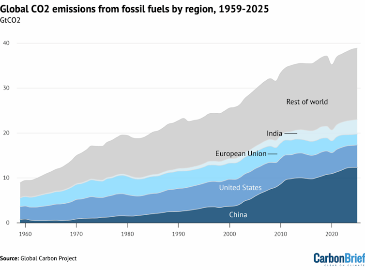
With the increasing focus on green energies, ammonia has become a globally important energy source and energy carrier. Moreover, ammonia is used in preparing various products such as fertilizer, plastics, fibers, explosives, pharmaceuticals, and others. Ammonia is mainly produced from the reaction of nitrogen and hydrogen from natural gas (brown ammonia) using a conventional technique called the Haber-Bosch process. As it is clear from (Fig. 5), this process accounts for CO2 footprint (releasing 1.9 tons CO2 for each ton of green NH3 produced and increased significantly in case of blue and brown ammonia). It is estimated that NH3 production contributed to 1.8 % of the global CO2 emissions [148].
Fig. 5. Energy requirements and CO2 footprint for brown, blue, and green Ammonia [150], [151], [152], [153], [154], [155]. (For interpretation of the references to colour in this figure legend, the reader is referred to the web version of this article.)
The transition to green ammonia production through hydropower electrolysis was realized since 1920 in Norway. However, replacing the Haber process with electrolysis from renewable sources requires further consideration regarding the costs, production capacity, material development, and excess renewable energy source [149]. Theoretically, the energy needed for green ammonia production through conventional high-pressure synthesis is 30 ± 5 GJ/tNH3. This has given priority to the transition toward direct NH3 production under milder conditions.
Current trends for NH3 production are driven toward the transition to mild temperature and direct ammonia synthesis. In the past few years, research and development paid considerable attention to electrochemical and photochemical ammonia synthesis because ammonia synthesis from water and nitrogen eliminates the intermediate hydrogen production step. It offers a route to store excess energy produced by solar or wind. Also, non-thermal plasma has shown promising results toward low temperature and pressure ammonia synthesis owing to their elevated electron temperature. Moreover, if the challenges toward this production method are appropriately handled, the process will be cost-effective and has zero carbon dioxide footprint. However, these methods still have many limitations that require further investigation to be viable for pilot and large-scale applications. Table 7 represents the pros, and cons of different routes for ammonia synthesis.
Table 7. Ammonia synthesis different technologies comparison.
Although all the synthesis routes still have considerable challenges, such as low efficiencies, high cost and negative environmental impacts. The indirect processes for ammonia production from hydrogen show promising results, and further research and development will accelerate green ammonia synthesis to achieve sustainable development. Investment, legislative laws and international/national policies also play significant roles in this matter.
3.1. Power to ammonia synthesis (Water Electrolysis)

Type of the electrolyzer
Eff. %
Cost
$/kwPressure (bar)
Comments
Ref.
AEL “Alkaline electrolyzer”
50–60
1000–5000
1–30
[51], [52], [53], [54]
PEM “polymer electrolyte membrane electrolyzer”
46–60
1500–2100
20–50
[52], [55], [56]
SOE “Solid oxide electrolyzer”
Up to 85 %
> 2000
1–15
[19], [52], [57]
3.2. Emerging ways for ammonia synthesis
3.2.1. Electrochemical ammonia production
3.2.1.1. Low-temperature electrochemical ammonia synthesis
T (°C)
Electrolyte
Cathode
Ammonia Yield (mol/s cm−2)
Ref.
50
AEM
Fe
380 × 10−12
[79]
80
Nafion
SmBaCuMO5+
870 × 10−10
[80]
80
Nafion
Sm1.5Sr0.5NiO4
105 × 10−10
[81]
80
SPSF
Sm1.5Sr0.5NiO4
103 × 10−10
Room T
Nafion
Fe/Fe3O4
111 × 10−10
[82]
Room T
AEM
Fe–CuS/C
686 × 10−12
[75]
50
AEM
RuPt
635 × 10−12
[83]
Room T
Nafion
Au nanorods
27 × 10−12
[84]
Room T
Nafion
Fe2O3-CNT
36 × 10−12
[71]
3.2.1.2. Molten-salt ammonia synthesis (Moderate Temperature)

T (°C)
Electrolyte
Cathode
Ammonia Yield (mol/s cm−2)
Ref
450
SDC-ternary carbonate composite electrolyte
La0.6Sr0.4Fe0.8Cu0.2O3−δ
539 × 10−11
[93]
450
LiAlO2 – (Li/Na/K)2CO3
Co3Mo3N-Ag
327 × 10−12
[94]
400
LiAlO2 – (Li/Na/K)2CO3
CoFe2O4-Ag
232 × 10−12
[95]
400
LiCl-KCl-CsCl + Li3N
Porous Ni/Ni
333 × 10−11
[86]
300
LiCl-KCl-CsCl + Li3N
Porous Ni/C
200 × 10−10
[87]
200
NaOH/KOH (Nano-Fe2O3)
Ni
100 × 10−10
[50]
400
LiCl, KCl, CsCl + Li3N
Al
333 × 10−10
[96]
T (°C)
Electrolyte
Cathode
Ammonia Yield
(mol/s cm-2)Ref.
550
BaZr0.7Ce0.2Y0.1O3 − δ
Ni-BZCY72
286 × 10−11
[102]
550
BZCY72
“BaZr0.8Y0.2O3 − δ “La0.6Sr0.4Co0.2Fe0.8O3-δ (LSCF)
850 × 10−13
[103]
500
BCY10
“BaCe0.9Y0.1O3 − δ“Ag-Pd
300 × 10−13
[104]
620
BZCY72
“BaZr0.7Ce0.2Y0.1O3 – δ”Ni-BZCY72
170 × 10−11
[105]
600
GDC “Ce0.9Gd0.1O2 − δ “
Pt
367 × 10−13
[106]
3.2.1.3. Solid-State ammonia production (High Temperature)


3.2.2. Electrochemical lithium metal cycling
3.2.3. Photocatalytic ammonia synthesis
T (°C)
Catalyst
Light radiation
Ammonia Yield
(µmol gcat−1h−1)Ref.
40
TiO2
Hg-Arc Lamp (UV)
4.17
[121]
40
0.2 wt% Fe-TiO2
Hg-Arc Lamp (UV)
11.5
[121]
25
Fe-doped TiO2
UV lamp
400
[129]
n/a
0.5 wt% Cr-TiO2
HWL lamp
2.12 µg m−2h−1
[123]
25
5 % RuCl3/TiO2
Xe lamp
4 μM·cm−2h−1
[130]
30
g-C3N4
sodium lamp
83.6
[131]
25
TiO2@C/g-C3N4
Xe lamp
250.6
[126]
38
Pt/TiO2
Hg lamp
9.3
[132]
38
Pt-CdS
Hg lamp
16.3
[132]
3.2.4. Nonthermal plasma ammonia synthesis
Plasma reactor type
Operating conditions
Type of electrode
NH3 rate
Ref
DBD discharge
N/A
Cu tangled
250 (ml min −1)
[141]
DBD discharge
200
Co–Ni Bimetal
1500 (μmol g−1h−1)
[142]
Advanced plasma reactor
Ambient conditions
(Ru) catalyst
2.67 (mmol gcat.−1 h−1)
[143]
Microwave plasma
327 to 427 °C
N/A
1.5 (mmol g−1)
[144]
DBD discharge
Ambient conditions
(Ru) catalyst
1.7 (g kWh−1)
[145]
DBD discharge
Ambient conditions
Au, Pt, Pd, Ag, or Cu electrodes
41.0 (μmol min−1) (Cu)
[146]
DBD discharge
140 °C
Ni supported on silica
N/A
[147]
3.3. Assessment and comparison of different NH3 technologies

Technology
Pros.
Cons.
Comments
Ref.
Electrochemical High-temperature NH3 production (Solid state)
1- Possibility for direct ammonia production from water and nitrogen;
2- The design of the cell is easy;
3- Low pressure required;
4- Zero carbon emissions and reactants can be generated on the same cell1- Low durability for the electrodes owing to high temperature;
2- Low formation rate and faradic efficiency;
3- High temperature require high power consumption;
4- Challenges related to the nitrogen triple bond dissociation on the surface catalystThis system reveals a potential for direct ammonia synthesis; however, many considerations with the cell and catalyst are still required
[84], [91], [63], [156], [157]
Electrochemical Medium-temperature NH3 Production (Molten state)
1- Possibility for direct ammonia production from water and nitrogen;
2- Lower operation temperatures;
3- Zero carbon emissions and reactants can be generated on the same cell1- Limited faradic efficiency and ammonia production rate;
2- The electrolyte is corrosive for the electrodes;
3- Environmental issues due to the corrosive electrolytes;
4- Challenges related to the nitrogen triple bond dissociation on the surface catalystIt is considered a clean energy direct ammonia synthesis; however, consideration should be taken with the electrolytes
Electrochemical Low-temperature ammonia synthesis
1- Direct ammonia production at very low temperatures < 100 °C;
2- Variant of electrolytes can be used;
3- Zero carbon emissions and reactants can be generated on the same cell1- Higher voltage is needed to overcome the overpotential;
2- low NH3 production rate and limited FE;
3- High capital cost of the technology;
4-Challenges related to the nitrogen triple bond dissociation on the surface catalystStill not viable for industrial applications
Photochemical NH3 Production
1- Possibility for direct ammonia production from water and nitrogen;
2- The reactor design is already an existing technology;
3- Low temperature synthesis;
4- Zero-carbon emission1- The main issue for this is the competing toward hydrogen evolution reaction;
2- Ammonia production rate is very low; 3- Challenges related to supply electrons through lightIt reveals the potential of using solar energy to transform water and nitrogen into O2 and NH3; however, considerable attention should be taken for developing photocatalyst that can reduce the band gap with a high active site and capable to inhibit HER. Furthermore, new reactor system design should be taken on consideration.
[158], [159], [160], [161]
Plasmatic NH3 Synthesis
1- The mean electron energies of non-thermal plasma, which is around 20 eV, make it ideal for room temperature synthesis;
2- Clean and carbon free production;
3- Small scale production at the site on interest1- The efficiency and conversion are very low;
2- Many challenges would face large scale productionStill this method requires more investigation to be viable for large scale production
[162], [163]
INDIRECT AMMONIA PRODUCTION FROM HYDROGEN
Water electrolysis
1- Lower complexity;
2- High purity of hydrogen;
3- Absence of emission during the process without taking the consideration of electricity source1- Indirect ammonia synthesis causing a lower ammonia efficiency around 70 % for electrolysis to produce hydrogen and then the efficiency associated to NH3 production;
2- The average energy consumption is between 52.5 and 70.1 kWh;
3- The environmental effects are 0.5 to 1.5 kg CO2-eq. /kg H2 for wind electricity, 1.3–3 kg CO2-eq. /kg H2 for solar electricity, and 0.5 to 1 kg CO2-eq. /kg H2 for nuclear electricity.The availability of this technology gives it the potential for direct industrial application
[164], [165], [166], [167]
Dark Fermentation
1- Simple reactor design;
2-Continous high yield of H2 production;
3- No light is needed for this process1- Indirect ammonia synthesis causing a lower ammonia efficiency around 70 % for electrolysis to produce hydrogen and then the efficiency associated to NH3 production;
2- Contribution on the CO2 emission 0.5 mol CO2/mole H2;
3- Production of volatile fatty acid;
4- Further gases separation is needed owing to the CO2Biological technologies might contribute to the sustainable development of green hydrogen production if the CO2 produced is properly handled
[98], [168], [169], [170]
4. Applications of ammonia in the energy sector
Besides the usage of ammonia in the chemical industry and as a fertilizer, it is a carbon-free fuel that has the potential in several energy sectors; that is summarized briefly in Fig. 6, and will be summarized in this section:
Fig. 6. Schematic diagram briefly describes the most promising application of ammonia rather than chemicals and fertilizer.

4.1. Ammonia-based fuel cells
Renewable energy resources such as geothermal, hydro, solar, tidal and wind energies have been considered eco-friendly technologies. However, these resources are sporadic as they depend on geological parameters, solar availability and intensity, wind speed, altitude, etc. [171]. Efficient energy storage and conversion devices are the best choices to store and convert such energies for energy-deficient periods. Fuel cells are energy conversion systems that are eco-friendly, compact, efficient, available in different sizes, and demonstrated promising results in different applications [172], [173]. Various fuel cell types depend on the operating temperature, membrane type, applications, or fuel type. Due to its simple structure, carbon-free, and sustainable energy source, hydrogen is considered the best fuel for fuel cells [174], [175]. Several studies demonstrated the effectiveness of the integration of the fuel cell in renewable energy resources within periods of low energy output [176]. But there are two main challenges facing the utilization of hydrogen as fuel, consisting of its transportation and storage [14], [177]. Hydrogen carriers such as methanol, ethanol, ammonia, hydrazine, etc., have been proposed to overcome such challenges. Among them, ammonia is considered a carbon-free hydrogen carrier with high hydrogen content (17.6 wt%). In contrast to hydrogen, ammonia is easier to transport and store. Thus ammonia could be used directly or indirectly as fuel in Fuel cells. Indirect ammonia fuel cell depends on converting ammonia to hydrogen, which is fuel in the fuel cells. The electrolysis of ammonia at 250 °C produced high-purity hydrogen that can be used directly at the fuel cell's anode [178], [179]. A system that consists of a combustion engine fueled with ammonia and hydrogen (produced from the dissociation of ammonia) was used to power a vehicle [180]. The overall energy efficiency of that system reached 61.89 %. A Direct ammonia fuel cell is a system that transforms the chemical energy contained in ammonia directly to electrical energy with high efficiency. With the widespread production of green ammonia, the interest in ammonia-based fuel cells increases. Fuel cells are considered the most efficient device to extract ammonia's energy with low or no environmental impact [181], [182]. There are four categories of ammonia-based fuel cells, i.e., alkaline ammonia fuel cell (MAFC “Molten alkaline ammonia fuel cell”), ammonia-based SOFC-H “Proton conducting electrolyte based solid oxide fuel cell”, and ammonia-base SOFC-O “oxygen anion conducting electrolyte based solid oxide fuel cell”, AAEFC “ammonia-based alkaline electrolyte fuel cells”, and ammonia-based MFC “microbial fuel cell”.
Ammonia-based SOFC operates at high temperatures (500–1000 °C). At such high temperatures, ammonia cracking and power generation are consolidated [183], [184]. The cost of such FCs is relatively low as there is no need for separate ammonia cracking unit. Moreover, such high temperatures increase the catalytic activity, so a non-precious catalyst is used. Also, such a high temperature enhances the electrolyte's ionic conductivity [185]. Ammonia-based SOFCs are classified into two types according to the electrolyte type; SOFC-H “proton-conducting electrolyte SOFC” and SOFC-O “oxygen anion conducting electrolyte SOFC” [186].
In this type of fuel cell, ammonia is fed at the anode of the FC, where it thermally decomposes over the anode catalyst into hydrogen, while air or oxygen is fed on the cathode side. Oxygen reduction into oxygen ions occurs at the cathode/electrolyte interface. The oxygen ions transfer to the anode side via the electrolyte, where electrochemical reactions occur at the anode/electrolyte interface, producing water vapour. The nitrogen production during the ammonia decomposition reduces the reversible reaction as it dilutes the hydrogen concentration, as can be seen in Fig. 7.
Fig. 7. Schematic diagram showing the principles of the asofc-o.
First, ammonia decomposed at the inlet of the anode surface as follows:(16)" role="presentation" style="box-sizing: border-box; margin: 0px; padding: 0px; display: inline-block; font-style: normal; font-weight: normal; line-height: normal; font-size: 14.4px; text-indent: 0px; text-align: left; text-transform: none; letter-spacing: normal; word-spacing: normal; overflow-wrap: normal; white-space: nowrap; float: none; direction: ltr; max-width: none; max-height: none; min-width: 0px; min-height: 0px; border: 0px; position: relative;" tabindex="0">
Then, the electrochemical reactions and overall reactions are shown in Eq. 17–19.
@ anode:(17)" role="presentation" style="box-sizing: border-box; margin: 0px; padding: 0px; display: inline-block; font-style: normal; font-weight: normal; line-height: normal; font-size: 14.4px; text-indent: 0px; text-align: left; text-transform: none; letter-spacing: normal; word-spacing: normal; overflow-wrap: normal; white-space: nowrap; float: none; direction: ltr; max-width: none; max-height: none; min-width: 0px; min-height: 0px; border: 0px; position: relative;" tabindex="0">
@ cathode:(18)" role="presentation" style="box-sizing: border-box; margin: 0px; padding: 0px; display: inline-block; font-style: normal; font-weight: normal; line-height: normal; font-size: 14.4px; text-indent: 0px; text-align: left; text-transform: none; letter-spacing: normal; word-spacing: normal; overflow-wrap: normal; white-space: nowrap; float: none; direction: ltr; max-width: none; max-height: none; min-width: 0px; min-height: 0px; border: 0px; position: relative;" tabindex="0">
The overall reaction is:(19)" role="presentation" style="box-sizing: border-box; margin: 0px; padding: 0px; display: inline-block; font-style: normal; font-weight: normal; line-height: normal; font-size: 14.4px; text-indent: 0px; text-align: left; text-transform: none; letter-spacing: normal; word-spacing: normal; overflow-wrap: normal; white-space: nowrap; float: none; direction: ltr; max-width: none; max-height: none; min-width: 0px; min-height: 0px; border: 0px; position: relative;" tabindex="0">
ASOFC-O is composed of the YSZ “Yittria stabilized zirconia” electrolyte doped with SDC “Samarium doped ceria”, SSC “Sm0.5Sr0.5Co3-δ” cathode, and nickel anode. The ASOFC-O could produce 168.1 mW/cm2 at 600 °C, compared with 191.8 mW/cm2 in the case of hydrogen-based SOFC-O. With the slightly lower power output in the case of the ASOFC-O would be related to the dilution effect of the nitrogen produced ta the anode from the ammonia dissociation [187]. This power increased with the operating temperature and/or efficient cell components. For instance, ASOFC-O fabricated of SSC cathode, nickel oxide anode, and SDC electrolyte (24 µm thick), generated a 467 mW/cm2 at 650 °C [188]. ASOFC-O with a nickel-based anode, BSCF “Ba0.5Sr0.5Co0.8Fe0.2O3-δ” cathode, and SDC electrolyte (10 µm) operated at 650 °C [189]. This ASOFC-O showed high power densities of 1190 and 1872 mW/cm2 using ammonia and hydrogen. YSZ electrolyte was also investigated in ASOFC-O but showed lower performance than those using SDC electrolyte. ASOFC-O with YSZ electrolyte, silver-based cathode and platinum-based anode was operated at 800 and 1000 °C, achieving 50 and 125 mW/cm2 [190]. The thickness of the electrolyte also affected the cell performance; for instance, an ASOFC-O using YSZ electrolyte (15 µm), LSM cathode, and nickel anode showed a 202 mW/cm2 at 800 °C [191]. Several studies have been done to check the effect of the electrolyte on cell performance [192], [193], [194].
Similar to the case of the ASOFC-O, ammonia decomposed at the inlet of the anode catalyst into hydrogen and nitrogen. However, in this case, the produced hydrogen is oxidized at the anode/electrolyte interface into hydrogen protons (H+), that migrate via the electrolyte membrane to the cathode side, as they combine with oxygen at the cathode/electrolyte interface producing water as can be seen in Eq. 20–22:
At the anode, the hydrogen generated from the dissociation of ammonia is oxidized, Eq. 20:(20)" role="presentation" style="box-sizing: border-box; margin: 0px; padding: 0px; display: inline-block; font-style: normal; font-weight: normal; line-height: normal; font-size: 14.4px; text-indent: 0px; text-align: left; text-transform: none; letter-spacing: normal; word-spacing: normal; overflow-wrap: normal; white-space: nowrap; float: none; direction: ltr; max-width: none; max-height: none; min-width: 0px; min-height: 0px; border: 0px; position: relative;" tabindex="0">
These protons combine with oxygen at the cathode/electrolyte interface as follows, Eq. 21:(21)
The overall reaction is similar to that in the case of the ASOFC-O, Eq. 19. Fig. 8 shows the schematic of the operating principles of ASOFC-H.
Fig. 8. Schematic diagram showing the principles of the asofc-h.
Compared to ASOFC-O, the formation of nitrogen oxides is avoided in the ASOFC-H, but the produced power is lower. BCG “gadolinium-doped barium cerate” is mainly used as the electrolyte in ASOFC-H. The performance of ASOFC-H with two different electrolytes BCG or BCGP “Gadolinium and Praseodymium-doped barium Cerate”, was investigated at 700 °C using platinum electrodes showing 25 and 35 mW cm−2 for BCG and BCGP, respectively [195], [196]. A mixed ionic and electronic conducting cermet anode (Ni-BCE) was investigated in platinum-based cathode ASOFC-H with BCGP electrolyte [197]. Compared to the platinum anode, The Ni-BCE anode showed superior catalytic activity toward ammonia oxidation, achieving a peak power density of 28 mW cm−2 (at 600 °C), while Pt anode showed 23 mW cm−2 at the same operating temperature. ASOFC-H incorporated with Ni-BCE anode realized a very stable performance for>500 h. The performance of ASOFC-H with BCGO “BaCe0.8 Gd0.2 O2.9” electrolyte, LCSO “La0.5 Sr0.5 CoO3– δ” cathode and Ni-based anode was investigated at a temperature ranging from 600 to 750 °C [198]. The cell's power output increased from 96 mW cm−2 @ 600 °C to 384 mW cm−2 @ 750 °C. A thin BCGO electrolyte (30 µm) was tested in ASOFC-H operated @ 600 °C, using CGO (Ce0.8Gd0.2O1.9)-Ni anode, and BSCFO “Ba0.5Sr0.5Co0.8Fe0.2O3−δ” -CGO cathode attained an OCV of 1.12 V and peak power of 147 mW cm−2 [199]. A BZCY “BaZr0.1Ce0.7Y0.2O3−δ” based electrolyte (35 μm) was also investigated in ASOFC-H using Ni-based anode and BSCF “Ba0.5Sr0.5Co0.8Fe0.2O3-δ” cathode acquired 420 mW cm−2 @ 700 °C [200]. The ASOFCs-H with the same electrolyte but using different electrolyte thicknesses and different cathodes were also examined. ASOFC-H with a thin electrolyte of 10 μm and GdBaCo2O5+x cathode achieved a 266 mW cm−2 [201], ASOFC-H with electrolyte thickness of 50 μm and LSC “La0.5Sr0.5CoO3−δ” cathode attained 330 mW cm−2 [202], and ASOFC-H with electrolyte thickness of 65 μm and BPY “Ba(Ce0.4Pr0.4Y0.2)O3−δ” cathode attained 270 mW cm−2 [203]. Moreover, BCNO “BaCe0.9Nd0.1O3−δ” electrolyte of 20 µm thickness was tested in ASOFC-H using nickel oxide-based anode, and LCSO cathode @ 700 °C attained 315 mW cm−2 [204].
In these ammonia-based fuel cells, oxygen from the air reacts with water at the cathode side forming hydroxide ions (anions). These ions transfer to the anode side via the electrolyte. The alkaline electrolyte may be aqueous in the case of AAEFC, such as sodium hydroxide or molten potassium hydroxide, as in the case of AAMFC. At the anode side of the molten or aqueous alkaline electrolyte fuel cell, the anions react with the fuel (ammonia), producing water, nitrogen, and electrons, as seen in Eq. 22 and 23:
@ anode(22)" role="presentation" style="box-sizing: border-box; margin: 0px; padding: 0px; display: inline-block; font-style: normal; font-weight: normal; line-height: normal; font-size: 14.4px; text-indent: 0px; text-align: left; text-transform: none; letter-spacing: normal; word-spacing: normal; overflow-wrap: normal; white-space: nowrap; float: none; direction: ltr; max-width: none; max-height: none; min-width: 0px; min-height: 0px; border: 0px; position: relative;" tabindex="0">
@ cathode(23)" role="presentation" style="box-sizing: border-box; margin: 0px; padding: 0px; display: inline-block; font-style: normal; font-weight: normal; line-height: normal; font-size: 14.4px; text-indent: 0px; text-align: left; text-transform: none; letter-spacing: normal; word-spacing: normal; overflow-wrap: normal; white-space: nowrap; float: none; direction: ltr; max-width: none; max-height: none; min-width: 0px; min-height: 0px; border: 0px; position: relative;" tabindex="0">
One of the main drawbacks of the hydroxide ions that it could react with CO2, producing carbonate ions, thereby decreasing the available hydroxide ions, and hence, reducing the ionic conductivity of the electrolyte, hence decreasing the fuel cell performance as seen in Eq. 24. Furthermore, carbonate compounds precipitates are formed in ammonia alkaline aqueous or molten electrolyte fuel cell.(24)" role="presentation" style="box-sizing: border-box; margin: 0px; padding: 0px; display: inline-block; font-style: normal; font-weight: normal; line-height: normal; font-size: 14.4px; text-indent: 0px; text-align: left; text-transform: none; letter-spacing: normal; word-spacing: normal; overflow-wrap: normal; white-space: nowrap; float: none; direction: ltr; max-width: none; max-height: none; min-width: 0px; min-height: 0px; border: 0px; position: relative;" tabindex="0">
Ammonia-based fuel cell with molten hydroxide electrolyte and porous nickel electrodes was constructed and operated at 200 to 450 °C. The cells showed 16 mW cm−2, which increased to 40 mW cm−2 @ 450 °C [205]. The same electrolyte was investigated using Pt electrodes operated at 200–220 °C [206]. A 10.5 mW cm−2 was realized at 200 °C and increased to 16 mW cm−2 at 220 °C. AAMFC operated at room temperature using CPPO “Chloroacetyl poly, 2,6-dimethyl-1,4-phenylene oxide”, PVA “polyvinyl alcohol” (CPPO-PVA) electrolyte membrane, MnO2/C cathode, and Chromium decorated nickel/carbon anode achieved 16 mW cm−2 [207].
MFC “microbial fuel cell” is a bio-electrochemical device used for simultaneous wastewater treatment and harvesting energy from wastes in the form of electricity [208], [209], [210]. Although the low power output of MFC, it has several advantages as the fuel is the wastewater that is contaminated with various organic materials, simple in design, operates at room temperature, uses the microbes in wastewater as the biocatalyst, and no need for precious cathode catalyst. The microorganism on the anaerobic anode chamber metabolites the organic wastes, generating electrons and protons that move to the cathode side, reacting with oxidant-producing water at the cathode side. Electrical energy is generated as the electrons flow from anode to the cathode. Ammonia-polluted wastewater could be used effectively as a substrate in MFC to obtain electricity. The ammonia-polluted wastewater was used as substrate in HND-ACMFC “heterotrophic nitrifying/denitrifying air–cathode fuel cell” [211]. The HND-ACMFC was investigated for long-term operation, 197 days, repeatedly, and it demonstrated an efficient removal of total nitrogen , ammonia, and COD of 95 %, 99 % and 91 %, respectively, with continuous electricity generation of 0.72 A m−3 and peak power of 100 mW m−3. Another study examined IVCW-MFC “integrated vertical flow constructed wetland microbial fuel cell”, for electricity generation and swine wastewater treatment [212]. The IVCW-MFC achieved 456 mW m−3, steady voltage output between 598 and 713 mV, and average removal efficiencies of 77.5 %, 75.13 % and 79.65 %, for NH4+–N, NO3–N, and COD, respectively.
4.1.1. Ammonia-based SOFC
4.1.1.1. ASOFC-O “Ammonia-fed oxygen anion conducting electrolyte-based SOFC”

4.1.1.2. ASOFC-H “ammonia-fed proton-conducting electrolyte-based solid oxide fuel cells”

4.1.2. AAMFC “Ammonia alkaline molten fuel cell” and AAEFC “ammonia alkaline electrolyte fuel cell”.
4.1.3. AMFC “Ammonia-based microbial fuel Cell”
4.2. Ammonia-based battery
S-TEGs “Solid state thermoelectric generators” are commonly used to transfer waste heat (thermal energy) to electrical power; however, the high cost of S-TEGs hinders their large-scale applications [213], [214]. Recently, TRBs “Thermally regenerative batteries” demonstrated an ability to convert heat (including waste heat resources) to electricity efficiently and at a reasonable price. TRAB “thermally regenerative ammonia-based battery” utilizes thermal distillation and redox reactions to transform the low-grade waste heat (<130 °C) to electricity using thermally regenerated electrolytes [215], [216]. Metal electrodes and ammonia combine to form a complex during the discharge process, which results in a potential difference that generates energy. During charging, the waste heat is utilized to extract ammonia from the anolyte and move it to the catholyte [217], [218]. There are two types of TRABs according to the electrode type, i.e., S-TRAB “single metallic” where both electrodes are made of the same metal [219], B-TRAB “bimetallic” where the two electrodes are made of different metals [220].
Cu-TRAB was constructed of copper mesh electrodes where 2 M ammonia was added to the anolyte using redox couples of “Cu(NH3)42+/Cu and Cu[221]/Cu” [222]. Copper-based S-TRAB generated 115 ± 1 W m−2, which increased to 136 ± 3 W m−2 by increasing the ammonia concentration to 3 M. The power doubled when another cell was added. Cu-TRAB was also constructed and examined at different operating temperatures [216]. The Cu-TRAB generated 95 ± 5 W m−2 and 236 ± 8 W m−2 at 23 °C and 72 °C, respectively. The enhancement of the power at higher temperatures was related to the decreased electrode overpotentials and the adequate copper oxidation at the anode. Moreover, the effect of flow rate, reactor design, and electrode pore density on the performance of Cu-TRAB was investigated [223]. The various reactor designs demonstrated varying mass transfer effects and various powers. The Cu-TRAB with a flow-through electrode on both sides (Cu-TRAB-FT) showed the highest peak power of 22.9 W m−2 due to the improved mass transfer of this electrode. Moreover, the optimum electrolyte flow rate and electrode pore density of Cu-TRAB-FT were 15 mL min−1 and 100 PPI “pores per linear inch”. Also, Cu-AFB “Copper-based ammonia flow battery” was designed and operated at different temperatures [221]. The Cu-AFB demonstrated power densities of 204 W m−2 and 280 W m−2 at 25 °C and 55 °C, respectively. The influence of operating parameters, including membrane type, electrode distance, electrode type, electrode area, ammonia and NH4NO3 concentrations on the performance of S-TRAB was assessed [224]. Different membranes, i.e., cation and anion exchange membranes of the same thickness (0.45 ± 0.025 mm), were tested. Different electrode types including Cobalt, copper or nickel sheets of the same dimensions (20 × 8 × 1 mm), were utilized as electrodes using NH4NO3 solution (5 mol·L−1 ) mixed with 0.1 mol·L−1 of Co(NO3)2, Cu(NO3)2, or Ni (NO3), respectively. Furthermore, different copper electrodes distances of 1.5, 4, 6, 8, 10, 12, and 14 cm, and different electrode areas of 1, 2, 6, 8, 10, 20, and 25 cm2 were also tested. The results exhibited that among different electrodes, the copper electrodes achieved the highest peak power density of 40 W·m−2. anion exchange membrane showed better Cu-TRAB performance than cation exchange membrane. The peak power density of Cu-TRAB increased with increasing electrode areas, ammonia and electrolyte concentrations over certain ranges. Additionally, definite concentrations of NH3 created tradeoffs between energy and power densities [225]. Increasing the NH3 concentration from 1 to 5 M decreases the energy density from 0.56 to 0.31 Wh/L, while the power increases from 11.2 to 28.5 mW cm−2. The decrease in energy density was related to NH3 crossover through the membrane during the Self-discharge of Cu-TRAB. A membrane-less microfluidic TRAB was also designed and operated at batch mode using pure copper electrodes or thick deposits of copper over compact graphite support electrodes [226]. Membrane-less microfluidic Cu- TRAB showed better power density than conventional Cu-TRAB operating under the same operating mode and conditions. The performance of membrane-less microfluidic TRAB was enhanced by replacing the pure copper electrodes with copper deposited on graphite electrodes that increased the power to 3.4 W m−2 at 50 °C. Cu/Ni composite electrodes were synthesized by electrodeposition of copper on nickel foams and investigated in TRABs [227]. Compared to Cu-TRAB, Cu/Ni-TRAB achieved the same power of 6.5 mW, but with higher anodic coulombic efficiency, 94 %, and considerably extended electrode operation time (>55 h).
Cu-TRABs suffered from unbalanced cathode deposition and anode dissolution rates during discharging cycles. To overcome such challenges, a Cu-TRAB using ligands was developed to stabilize Cu(I) and Cu[221] ions·NH3(aq) and Br−(aq) ligands were used in Cu-TRAB operated at 25 °C achieving a cell potential difference of 695 ± 2 mV, 350 W m−2 and high Coulombic efficiency (>90 %) [228]. The system's energy storage density was twice that reported for alternated Cu-TRAB chemistries and can reach four times higher. A steady and reversible electrode reaction was also accomplished using inert carbon electrodes and silver salts throughout a number of cycles [229]. Under bath mode test, 23 W m−2 was achieved, which is 64 % higher than that generated using Cu-TRAB. Furthermore, a 30 W m−2 was stable over 100 cycles under continuous flow operation, realizing superior reversibility. Cu/Zn-TRAB, using copper and zinc electrodes was constructed and examined at different temperatures (10–45 °C) [218]. Peak power of 389 W m−2 was achieved and increased to 723 ± 45 W m−2 by increasing the temperature from 10 to 40 °C with linear slope of 12.25 W m − 2 °C − 1. However, further increases in the temperature resulted in decreasing the power output. Copper/zinc bimetallic TRA based flow battery (Cu/Zn-TRAFB) was also developed, realizing a voltage discharge of 1.38 V and 535 W m−2 with redox couples [Cu[221]/Cu and Zn(NH3)42+/Zn] [230]. A power of 1070 (535 W m−2) could be achieved by connecting two cells (parallel or series).
4.3. Ammonia as fuel in ignition engines (AIE)
The automobile industry is one of the most pollutant sectors of the environment where it is based on combustion engines powered by fossil fuels. The decarbonization of power generation, marine and automotive markets is compulsory for limiting global warming and meeting the emissions of greenhouse gases. Hydrogen is considered a carbonless fuel that could be implemented with diesel in IE to decrease carbon emissions. But hydrogen is compressed at high pressure, and thus, it is a dangerous and expensive approach. Therefore, hydrogen carriers are considered a good candidate for diesel-based engines. Ammonia is deemed a hydrogen carrier and could be used effectively as an alternative fuel in CIE. Ammonia could be burned with any fuels with low auto-ignition temperature or diesel (dual fuel combustion, DFC), thereby decreasing the carbon-based emissions. But NOx emissions and high unburned ammonia are the main demerits of the DFC approach, and thus the after-treatment system is needed. Consequently, compression ignition using ammonia could be a proper solution for heavy-duty, marine and power generation applications. marine.
In 2007, Ammonia and gasoline-powered vehicle were designed and tested from Detroit to San Francisco [231]. In 2013, Toyota “Marangoni GT86 ECO” developed the first ammonia-fueled racing car that operated with ammonia fuel up to 2800 rpm while gasoline fuel was used at a higher speed [161]. In 2014, a vehicle that was partly fuelled with 70 % ammonia “ port injection” and 30 % gasoline “direct injection” was designed and operated successfully by the Korean Institute of Energy Research [232]. In the same year, a carbon-free hydrogen ammonia tractor was evolved by a Nevada corporation, “HEC Inc.” [233]. Newly, ammonia/hydrogen-fueled vehicles were developed using carbon-free hybrid system as hydrogen was produced by the electrochemical ammonia splitting [234].
Ammonia is the perfect fuel for marine and power generation applications [235], [236]. Marine and power generation are not space-constrained compared to automotive applications as they could be implemented with auxiliary equipment to reduce NOx emissions. Ammonia has been proposed as a favourable power-to-liquid approach for establishing a hydrogen economy [237]. Moreover, A company, “MAN Energy Solutions multinational company” plans to replace the dual-fuel marine engine (fueled with liquefied petroleum gas and diesel) with an ammonia-based engine [238], [239].
5. Key barriers toward green ammonia:
Scaling up direct green ammonia synthesis needs a new infrastructure framework and policies to support and overcome their barriers. The most obvious barrier to green ammonia synthesis is the capital investment costs. Green ammonia is produced through the Haber process using green hydrogen and nitrogen. Therefore, the main contributor to the capital cost is the cost of the electrolyzer and the cost of building wind and solar farms. Furthermore, there are many barriers to the evolution of green ammonia, such as technical, environmental, social and economic barriers that need policies and regulations to support limitations. The main barriers affecting the growth of green ammonia and policy support for them is shown in Fig. 9. Although there are many orientations toward green energy production, the percentage is still very small compared to conventional ways, mainly due to some barriers and challenges that must be solved for their industrial-scale applications.
Fig. 9. Different barriers affecting the growth of green ammonia and policy support for them. (For interpretation of the references to colour in this figure legend, the reader is referred to the web version of this article.)

5.1. Environmental barriers
The direct environmental effect of ammonia is related to its level in the environment. Ammonia has severe health issues for humans and other living creatures. Therefore, the exposure to ammonia, whether as a gas in the atmosphere, liquid, or fertilizer, must be within a definite limit. Another environmental impact of ammonia is related to its production method, usually associated with CO2 emissions from fossil fuels being used for hydrogen production, N2 separation from the air, and nitrogen reduction into ammonia NH3 [98]. Furthermore, ammonia as a chemical has several environmental impacts that must be considered during handling and storage [240], [241], [242]. The environmental impacts of ammonia are seriously considered as there is rapid growth and a need for ammonia as an energy source that is competitive with fossil fuels. The different environmental impacts of ammonia are summarized as follows:
- •
Green House Gases (GHGs) contribution: Industrial ammonia production has increased to reach>170,000 tons of produced ammonia, contributing as the second most produced chemical. However, most of the current ammonia production methods depend on conventional fuel-burning yielding ammonia, contributing to CO2 emissions at around 1.8 % [243]. For instance, in the case of using conventional fuel for NH3 production, the amount of CO2 produced is around 2.2 kg CO2/ kg NH3 [98]. Therefore, CO2 emissions plus the unreacted methane (source of hydrogen) will directly affect global warming by increasing the GHG. On the other hand, the main contribution of producing green ammonia from a direct and clean energy source could reduce the carbon footprint by around 90 %, contributing to about 1.7 % of the global carbon dioxide emissions footprint [45], [244], [245].
- •
Marine and ground life contribution (disturbance of ecological balance): The release of ammonia into the atmosphere will react with moisture producing ammonium that fall back to the earth as rainfall. Such ammonium in the rainfall will be converted to nitrates by the soil's bacteria, causing an increase in the soil's osmotic concentration [246]. Another aspects of ammonia gas at the atmosphere is the formation of ammonium sulphate casued by the reaction of ammonia gas with sulfuric or nitric acid vapours at the atmosphere to form small particles known as aerosols [247]. This will cause an increase in the soil pH, soil acidification, and direct toxic damage to essential nutrients found in the soil. Moving to ammonia effect to the aquatic ecosystem if it is directly spilt to surface water or its vapor cloud is allowed to reach water (Fig. 10). A concentration of only 0.02 ppm is enough to kill sensitive marine creatures [248], [249]. This can be mitigated during the production of green ammonia by following proper safety strategies, including fast detection, leak detection, emission capture and treatment.

Fig. 10. A schematic diagram for the impact of ammonia on surface water and marine life.
- •
Human life contribution: Ammonia is corrosive, and its impact on human health depends on the average weighted time and exposure dose (Table 8). Ammonia can significantly impact human health and the environment because it forms a strong basic solution that irritates the skin, the respiratory system, and the eyes. A 5 ppm of ammonia is the threshold limit for the pungent order; this can act as a warning of NH3 presence in the environment. Below 50 ppm, there is no recorded effect on the human; however, severe noise and throat irritation are recorded at 134 ppm. Above 2000 ppm, the person might die within a minute owing to a lack of oxygen and severe skin blisters and burns [250]. The experimental findings by Franks et al. [251] shows that the broad use of dangerous toxic load for ammonia toxicity could be calculated from the following equation (Eq. 16):
Table 8. Exposure effect on human beings [252], [253], [254].
Exposure (ppm) Body effect Permissible Exposure 50 ppm No recorded effect No effect 134 ppm Rhinitis symptoms 8 h 700 ppm Severe rhinitis symptoms and possible loss of sight 1 h 1,700 ppm Death if not treated urgently owing to severe lung damage Not permitted 2,000 ppm Chemical burns Not permitted 5,000 ppm Suffocation might die directly Not permitted
Where c is the concentration of ammonia in ppm and t is the exposure time.
- •
Land availability: the available land for new green ammonia production and storage is limited; therefore, expanding an existing plant is highly recommended. Hence, future studies should focus on developing and upgrading conventional ammonia production plants.
- •
Landscape and visual impact: This requires a technical study to assess the potential impact on the visual environment that ammonia projects can cause on the local community. It is about studying different locational installations, visual characterization, and the social life of the place. For example, a simple development was suggested based on the method of the landscape and visual impact of ammonia at the Yara Pilbara ammonia plant [255].
5.2. Technical barriers
Technical barriers are not only referred to the capacity, feasibility, infrastructure, and viability but also the lack of technical expertise and labour. For instance, a capacity barrier- producing green ammonia at a large scale would create an inability to handle and store the large capacity of ammonia which can cause severe problems to the ammonia infrastructure. The potential of renewable energy, wind and solar, to produce green ammonia is the major contribution to its green synthesis. This will raise another technical barrier because of the need to implement renewable energy projects for ammonia synthesis. Some other barriers, such as efficiency for direct green NH3 synthesis, availability, reliability, and maturity, are also worth mentioning. The technical criteria for green ammonia can be summarized as follows:
- o
Efficiency: It is defined as the ratio of the input energy over the output energy. The current trends are moving toward producing green ammonia through renewable sources (solar, tidal, or wind) to power an electrolyzer and air separation unit. The process efficiency can reach up to 83 % by involving a hybrid system consisting of high temperature operating system with heat integrations [47]. However, unconventional methods for direct ammonia (photosynthesis, electrochemical methods, low-temperature synthesis, and non-thermal plasmatic synthesis) are preferable. The main challenge facing these methods is their low efficiency. Fortunately, research and development are progressing toward increasing their efficiency up to 60 % using electrochemical methods [256].
- o
Availability: Green ammonia synthesis has existed from 1920s to the 1970s in Norway using a hydro-powered electrolysis plant. Nowadays, the switch to green synthesis is mainly concerned with the electrolyser's production cost and capacity [149]. However, the direct unconventional methods for green ammonia synthesis are still not viable for industrial applications, which requires further research.
- o
Decentralization; a locality of renewable energies where renewable energy differs from one country to another and even in the same country from one region to another. This puts the burden on the feasibility and economic studies where the accuracy of each study is mandatory to investigate each plant independently.
- o
Capacity barriers: Currently, the main barriers to green ammonia production are directly related to the production of green hydrogen because the available methods utilize hydrogen as an intermediate feedstock to produce green ammonia. Therefore, their capacity barriers would be concerned with electrolyzer capacity if power to ammonia synthesis was used.
- o
Storage: This is one of the main barriers. Commonly, ammonia is transferred and stored as a liquified compressed gas in either compressed gas at atmospheric temperature, refrigerated at atmospheric pressure, or intermediate pressure and temperature (semi-refrigerated state). Most importantly, the storage areas should be free from flammable materials and oxidiser sparks and must be well ventilated [257]. There are three methods for storing ammonia:
- 1-
Storing ammonia under high pressure (15–18 bars) at room temperature using spherical or cylindrical vessels with a capacity up to 2000 tons.
- 2-
Storage of ammonia at low temperatures (– 33 °C) and a pressure around (1.1 to 1.2 bar) using insulated vertical cylindrical tanks with a capacity up to 50,000 tons.
- 3-
Intermediate pressure storage at 0 °C using insulated reduced-pressure spherical vessels with a capacity up to 2500 tons.
- 1-
Compressed gas at atmospheric temperature and refrigerated at atmospheric pressure are the most common ways used to store ammonia. Initially, a high-pressure system (bullets and Horton spheres) was the dominant method to store ammonia, with a capacity reaching up to 2000 tons. However, low-pressure storage was later preferable to high-pressure for two reasons: 1- Capital requirements are lower per unit volume, and 2- Considerably safer than spherical ammonia storage under high pressure. Currently, the large industrial scale has shown a great interest in refrigerated ammonia storage at ambient pressure owing to the high-capacity storage [258], [259].
For pressure storage, cylindrical tanks can upstand up to 25 bar pressure. Compared to spherical tanks, maximum design pressure should not exceed 16 bar to prevent a wall thickness above 30 mm. Pressure storage is very economical for low quantities of ammonia needed in down streams unit processing ammonia and for services that require loading and unloading pressurized ammonia using tank cars, trucks, rail, and marine [260], [261].
Currently, refrigerated ammonia storage is preferred owing to its lower capital cost per unit volume compared to other methods and the higher volume capacity. Furthermore, this method is very convenient for loading and unloading refrigerated vehicles in ammonia synthesis plants. For refrigerated storage at –33 °C, many tanks configuration are available for a storage capacity up to 50,000 tons [262], [263]. The main types of atmospheric ammonia storage tanks are:
- 1-
Single-wall steel tanks with external insulation (made of rockwool or foam insulation) are sometimes surrounded by concrete bunds to prevent pollution.
- 2-
Steel tanks with double walls and perlite insulation in between the walls (double wall tanks). This type of tank can also be found in two different configurations depending on the insulation type. The first one is with insulation on the annular space that needs a full shutdown in case of an inner tank frailer. The second type, which contains outer insulation, offers a longer operational time in case of inside tank failure. Table 9 provides a summary of the different ammonia energy storage systems.
Table 9. Summary of different storage techniques for ammonia [258], [259], [260], [261], [262], [263].
Property Comments Pressure Storage System suitability - 1-
Small amount of ammonia
Entrance or exist from system pipelines.
When it is used as an intermediate chemical stock
Typical Pressure storage 16–18 bar Storage capacity Up to 2000 tons Design temperature 25 °C Refrigerated Storage System suitability - 1-
Large scale ammonia storage.
Marine transportation of large amount of ammonia.
In facilities that require ammonia to be cooled.
Typical Pressure storage 1.1–1.3 bar Storage capacity Up to 50,000 tons Design temperature –33 °C - 1-
- o
Research and development Lack of comparative studies between green ammonia and conventional ones equipped with carbon capture and storage. Indirect research is also required, such as life cycle assessments of resources used in renewable energies, such as terbium and dysprosium in wind generation, germanium, tellurium, indium and selenium in solar energy, etc. Intensive studies are needed before transitioning from the conventional Haber-Bosch process to modern electrochemical synthesis. The thermodynamic potential to activate nitrogen gas needs efficient catalysts that do not simultaneously accelerate hydrogen evolution [188]. There is a research gap in ammonia technology, such as the difficulty in separating from unreacted materials and, thus, low yield of ammonia at low pressure and searching for unconventional, highly selective and efficient catalysts.
5.3. Economic Barriers:
Compared with other competing technologies, the economic barriers to green ammonia production are mainly concerned with its high capital and operational costs (CAPEX and OPEX). The capital cost includes the electrolysis for hydrogen production, air separation unit, renewable energy, purification units, Harber-Bosch ammonia facility, storage units, plant auxiliaries, and civil works. Operational cost includes the availability of water, power source, labor cost, maintenance, land leasing, etc. The following are the main points that are related to the economic barriers:
- o
Investment cost: This includes CAPEX cost, electricity, labor, maintenance, land lease or purchase. Guerra and his research group [264] did a technical–economic analysis for green ammonia synthesis (123,400 t year−1) using an electrolyzer stack of 164.21 MW. The investment cost for an ammonia production plant was estimated to be 144,375,000 €, plus OPEX of more than a million per year. However, 7.2 year payback period was estimated with a net present value of 88,300,000 €.
- o
Energy cost: One of green ammonia's main challenges is the high cost of renewable sources (CAPEX of the renewable energy plant). This concern is seriously considered when considering the price of energy from conventional fuels. Sanchez and Martin [265] developed a model for green ammonia synthesis from air and water. Their study estimated that the project cost of green ammonia could be lower to 1.36 € kg−1. However, the high CAPEX and OPEX of producing green ammonia are still higher, almost triple using conventional fuel; thus, using green ammonia in the energy sector is nearly-four times higher in price than conventional fuel [266]. Green ammonia production has to be trustable to receive funds from all over the world, not only limited to developing countries. Still, several countries consider the support of green ammonia projects is non-economical compared to those powered by fossil fuels. Luke and Alcantara [25] investigated the Levelized cost of electricity (LOCE) for green ammonia synthesis using electrolyzer power by renewable energy (wind and solar) in 534 locations in over 70 countries. They expected a lower LOCE to be achieved by 2030 up to 310 $ t−1 with a price of 16.6 $ GJ−1 compared to a current price of 25.4 $ GJ−1. This study shows that green ammonia might be comparable to conventional fuels, i.e., Kerosene (8.7 – 18.3 $ GJ−1). Public and private finance can significantly promote investment in green ammonia] [187].
5.4. Policies and regulations
Green ammonia is still at its earliest stages of satisfying the global need for ammonia and its application in the energy sector. Some of these barriers are economic, financial, technical, and social. Therefore, it needs policy support to help in removing/decreasing these barriers and thus transfer green ammonia into a viable production method.
The main barriers to green ammonia synthesis are the high investment cost and energy requirements. According to the International Renewable Energy Agency, by 2050, the demand for green hydrogen will significantly increase to (134 to 159 million tons) which will require 1,775 GW of offshore wind farms, 2,243 GW of onshore wind, 4,240 GW of solar PV to satisfy this amount of green hydrogen production [267]. This is also true for green ammonia production because the main feedstock for its synthesis is hydrogen, and NH3 is considered a feasible way to store and transport green hydrogen. The high electrolyzers' CAPEX and renewable energy costs can be overcome by establishing a proper supporting policy. For example, tackling electrolysers' high costs can support research, economic scale, and innovation. The most important policy is closing the significant cost gaps between brown and green ammonia production. There are also many technical barriers affecting the infrastructure of green ammonia. One of the most significant barriers is direct ammonia synthesis without the need for the intermediate step for hydrogen production. Direct green ammonia production from water and air would be a significant step toward minimizing the production cost of ammonia. Another important policy is supporting green ammonia production in countries with plenty of renewable energy sources.
Ammonia is essential in energy as a zero-carbon fuel source, hydrogen carrier, and potential fuel in marine transport. According to the International Renewable Energy Agency, the insertion of green ammonia in the energy sector will significantly impact the global temperature rise by 1.5 °C and contribute toward a zero-carbon emission energy policy [268]. Like other sectors, cost plays the most obstacles to the development of the green ammonia sector. For instance, there is a gap between conventional and renewable fuels in terms of energy content and price. Unfortunately, green ammonia is almost four times higher than that grey ammonia (produced from natural gas). Therefore, there should be policies that consider the cost of the reserved CO2 emissions in the case of using green ammonia. Furthermore, safe policy attention should be taken to satisfy the obstacles of shipping and storing green ammonia.
6. Contribution of green ammonia to sustainable development goals, SDGs
In 2015, The United Nations reported 17 SDGs to be targeted by 2030 (Fig. 11). These goals are interconnected to ensure a safe and healthy life for everybody. The SDGs aim to end all forms of hunger and poverty everywhere and protect the ecosystems and conserve natural resources for future generations. In this context, The UN's strategy is to protect life on land and even below the water, produce green renewable energy, mitigate climate change and finally consolidate the relationship between the above SDGs [269]. The SGDs can be classified into three main categories; group 1 (SDG1-SDG6): SDGs focus on humans; group 2 (SDG7-SDG12): SDGs related to community and group 3 (SDG13-SDG17): SDGs related to the whole planet.
Fig. 11. The sustainable development goals (SDGs), https://sdgs.un.org/goals.

Green ammonia is directly related to some of these goals, namely; SDG2 “zero hunger”, SDG3 “good health and well-being”, SDG6 “clean water and sanitation”, SDG7 “affordable and clean energy”, SDG8 “decent work and economic growth”, SDG9 “industry and infrastructure”, SDG12 “responsible consumption/production” and SDG13 “climate action”. The following sections discuss the contribution of green ammonia to these SDGs.
All crops utilize nitrogen, with a special focus on wheat, maize and rice, where they account for higher than 50 % of the total demand for nitrogen-based fertilizer Globally (Fig. 12). Maize and rice have the widest application rates for the nitrogen-based fertilizer range, with an average of 98 and 96 kg N/ha, respectively. Some crops can directly fix nitrogen from the atmosphere, such as soybeans, peanuts, palm and clover, leading to less or zero fertilizer requirements [270].
Fig. 12. Nitrogen-based fertilizer demand and application rate of the main crop, , .
adapted from [270]https://iea.blob.core.windows.net/assets/6ee41bb9-8e81-4b64-8701-2acc064ff6e4/AmmoniaTechnologyRoadmap.pdf Feeding ∼80 % of the population worldwide depends mainly on ammonia-based fertilizer (ABF). Recently, the focus has been to transform the production process from the Haber-Bosch process, which consumes intensive -capital cost and -energy and uses fossil feedstock such as coal, to green ammonia technology, which depends on renewable energy such as hydropower, solar, and wind. Production of green ammonia yields social and economic benefits, such as producing fertilizers locally using the localized resources of renewable energy instead of importing fertilizers. Additionally, green ammonia served as a buffer to balance the seasonal variations of renewable energies, yielding consistent power needed for the development foundation. The possibility of combining renewable electricity with Haber-Bosch could occur via developing hydrogen from water electrolysis and separating nitrogen from the air via pressure-based adsorption. Haber–Bosch process is the traditional route for ABF production at a large scale. Agricultural production is significantly dropped due to soil nutrient depletion (nitrogen, phosphorous, and potassium). For this reason, around 80 % of 160 million tons/y of ammonia is utilized in fertilizers production, contributing to feeding > 70 % of the world's population, which nearly represents 50 % of the nitrogen in the human body. On the other hand, green ammonia plays a significant indirect role in nutrition. Animal production is directly proportional to grasses and plants, whose productivity is related to ABF. However, increasing grass production has lower environmental effects and higher efficiency than feed concentration; owning to that feed concentration needs considerably higher resources than pasture to yield and generate higher emissions. It was estimated that the farm had the lowest carbon footprint when sequestration was included [271]. Fig. 13 concludes the main factors that control the impact of green ammonia on SDG2.
Fig. 13. Inputs, outputs and the main factors for green ammonia contribution in SDG2. (For interpretation of the references to colour in this figure legend, the reader is referred to the web version of this article.)
The impact of green ammonia on human health could be assessed by evaluating its acidification, human toxicity, eco-toxicity, carcinogens, ozone depletion potential, and abiotic depletion impacts. Ammonia deposition yields eutrophication and acidification, and it is highly recommended to consider these values for accuracy purposes and subsequent mitigation strategies. For example, NH3 contributes to ∼ 95.5 in farm acidification. However, intensification increased NH3 emissions owing to the increase in fertilizer quantities. The eutrophication and NH3 emissions were reported as 86 %–94 % and 41 %–42 %, respectively [271]. Ammonia emissions which act for 13 % of agricultural emissions, increase the population's exposure to particulate matter by 0.36 μg /m3 on average [272]. However, lowering air pollution yielded a reduction in the particulate matters-based avoidable deaths by 2,804–8,249 in the year 2010 and 9,870–23,100 in 2020, pollution control policies have numerous advantages that minimize PM -and O3 -based mortalities by about 23 % during the period from 2015 to 2030 [273], [274]. It was reported that the potential global warming yields from coal gasification and steam methane reformation are 3.85 and 3.03 kg CO2-eq/kg NH3 produced, respectively. The minimum global warming (0.378 kg/kg ammonia) is recorded by biomass gasification, while steam methane reformation yields high abiotic depletion compared with other synthesis routes: 0.026 kg Sb-eq/kg NH3 [275]. Replacing conventional ammonia with green ones will minimize these negative impacts since green technology is based on renewable energies.
The ammonia production could occur via a coal-based ammonia synthesis approach which involves coal mining, washing, transportation, and ammonia production. The system is similar to the first approach for the coke oven gas-based ammonia synthesis route, with an additional coal coking stage. The system includes natural gas exploitation and transportation and ammonia production for the natural gas-based ammonia synthesis approach. It is worth noting that, for all conventional approaches to ammonia synthesis, there is wastewater polluted with contaminants released into the ecosystem [181]. The eutrophication potential is calculated from electricity consumption, the coal-burning, which generates nitrogen oxide, and wastewater discharged from the coking process that involves numerous contaminants such as chemical oxygen demand, phosphorus, and nitrogen. All of these constituents increased the eutrophication potential. The eutrophication potentials of natural gas-, coal- and coke oven gas-based ammonia are 0.0012, 0.0012 and 0.0016 kg phosphate-eq. The photochemical ozone creation potentials of natural gas-, coal- and coke oven gas-based ammonia are 0.599, 0.871 and 1.10 g ethene-eq [181]. The emissions related to water pollution and acidification (kg SO2-eq) are increased as more nitrogen-based fertilizers are applied in the agricultural sector [182]. Hence, consuming much more conventional ammonia should be replaced by green one to mitigate the negative impact on the ecosystem with a special focus on agricultural wastewater.
Green ammonia is the synthesis of ammonia using renewable energy, air and water. This zero-carbon energy storage vector has significant energy applications owing to its availability in different geographies and low cost of transporting and storing compared to the requirements of underground hydrogen storage or geological storage of captured carbon, Fig. 14. Ammonia can be easily stored as a liquid via pressurizing at 9 bar ambient temperature or cooling to –33 °C; the process doesn’t involve significant losses. Ammonia can be easily and safely transported in carbon-steel pipelines, ships, rail cars, and trucks. Also, plants' conversion from natural gas and oil into green ammonia is easy since the latter is used in the same pipelines with minor modifications. Moreover, 50 % much more energy could be delivered in case of the replacement of natural gas with liquid ammonia owing to the higher volumetric energy density of ammonia [276]. The typical storage tank has a capacity of liquefied NH3 up to 30,000 Mt, equivalent to 190 GW (H2 reformation from NH3), corresponding to 0.1 US$/kWh capital cost [277].
Fig. 14. The main contributions of green ammonia in the energy sector. (For interpretation of the references to colour in this figure legend, the reader is referred to the web version of this article.)
The power2ammonia2power technology is based on multidisciplinary connections where the battolysers provide the grid with power. The grid can also provide the ammonia production plant with power when the battolysers are discharged or/and the wind is weak in order to maintain the system heated and pressurized. However, no backup system is required. The system is characterized by flexibility, where excess ammonia can be introduced from an external source [278].
Green ammonia can be directly combusted in gas turbines, reciprocating engines, or electrochemically dissociated in fuel cells. Although there is a limitation in its implementation in current Otto cycle engines owing to its narrow flammability range, the NH3-based engine was designed and constructed for bus engines during the 2nd World War. To eliminate nitrous oxide formation during NH3 combustion, catalytic cracking and sodium-amide processes are suggested for the NH3 decomposition into its elements. The developed hydrogen can be efficiently combusted in gas turbines or fuel cells [277].
Transforming hydrogen into ammonia is essential to decrease the final cost of highly tumbling renewable electricity in an entirely green energy system [279]. By 2040, green ammonia will be an economic competitor fuel for zero-carbon electricity using efficient gas turbine power plants. The estimated Levelized cost of electricity (LCOE) for green ammonia at a power plant capacity of 25 % is 156–185 €/MWh in 2040, assuming a fuel price of 355 €/t. This cost of electricity is considerably less than bio-energy and coal plants coupled with carbon capture and storage and nuclear power. Also, it is comparable with natural gas-based power plants with post-combustion carbon capture and storage. The additional costs of 28 €/MWh owning to cracking of ammonia to hydrogen in gas turbines recommends the development of turbine technologies which are compatible with ammonia in the long term.
It was estimated that the Levelized cost of green ammonia ranges from 208 €/t to 450 €/t in 2040 according to the capital cost, solar PV cost, and electrolyzer costs. The local price of electricity is the main indicator of economic competitiveness for replacing traditional ammonia with green one. However, the economic impact of green ammonia could be clear by integrating its production plant with the national grid. This is attributed to the variation in prices of locally available or/and imported fuels. Also, some grids need varied capacity-utilization rates of dispatchable energy resources. Future research should focus on the considerations of these factors for the localized grid and regional scale as well as addressing other aspects such as a contradiction between electricity demand and cheap renewable supply such as in Japan, variation of seasonable renewable resources, the price of alternative approaches such as the low cost of gas in the USA which promote carbon capture and storage technologies, flexibility requirements, and legislative laws towards decarbonization.
The economic impacts of developing green ammonia-based fertilizer with the aid of hydropower show that the process determines ∼216 M€, equivalent to ∼165 % investment return for a net present value of 30 years compared to imported fertilizers. For example, this yields a saving of at least 50 M US dollars for importing rice. Additionally, green ammonia can compensate for seasonal fluctuations of hydropower ranging from 900 to 50 MW and provide additional power up to 370 MW [280]. A techno-economic analysis showed that transforming from small-scale (10 kW) to large-scale (10 MW) reduces the minimum hydrogen selling prices from 7.03 USD/kg to 3.98 USD/kg. Moreover, sensitivity analyses showed that H2 selling prices might be minimized by 50 %. The H2 produced from green NH3 reported significant CO2 reduction by 78–95 % (kg CO2/kg H2) compared to traditional methods such as steam methane reforming, biomass gasification, etc. [278].
Ammonia is the second largest product in the chemical industry sector worldwide after sulfuric acid. Also, it is the main precursor for synthetic fertilizers (urea, ammonium phosphate, and ammonium nitrate). Moreover, it is one of the raw materials for the production of numerous nitrogen-based chemicals (hydrazine (N2H4), urea (CO(NH2)2), ammonia carbonate ((NH4)2CO3), nitric acid, and ammonia borane (NH3BH3)), and capturing agent for acidic gaseous. Also, it is used in refrigerators and air-conditioners, manufacturing of acids, explosives, fibers, papers, plastics, polymers, and alternative fuel in ICE and FCs for power generation with/or without reforming. Ammonia production increased from 137 Mtons in 2012 to 140 Mtons in 2018; China, Russia, USA and India recorded the highest ammonia production with 31.4 %, 10 %, 8.9 %, and 7.8 %, respectively. To achieve sustainability, green hydrogen derived from renewable energy should be promoted to minimize greenhouse gas emissions and fossil fuel consumption [281], [282], [283]. Green hydrogen could be supplied from renewable energy-based water electrolysis and biomass gasification [13], [284]. A biomass-based ammonia production plant was compared to a natural gas-based. The exergy efficiencies of the biomass- and natural gas-based ammonia plants are 41.3 % and 65.8 %, respectively. Also, the elevated-temperature electrolysis achieved better integration with ammonia production facilities than low-temperature-based technologies owing to their high electrical efficiencies and heat integration. A techno-economic feasibility study of green ammonia production versus traditional one with a reference capacity 50 kton/y showed that biomass-to-ammonia is the most exothermic process with considerable limitations because of the immense heat required for acid gas scavenges. The power-to-ammonia recorded the maximum efficiency (74 %) compared to biomass-to-ammonia (44 %) and methane-to-ammonia (61 %). The production cost of one ton of ammonia using a biomass-based plant achieved 450 US $, equivalent to a payback higher than six years, while the cost of one ton of ammonia developed from a methane-based plant is 400 US $, with a payback of 5 years. The power-based plant wasn’t economically feasible because of high electricity and stack costs. However, the power-based ammonia production plant can be a competitor when the payback time is < 5 years; production of solid oxide could occur at full scale and increment of renewable power penetration [285].
The recent interest in using green ammonia for decarbonization shipping is a clear indicator of the numerous advantages of green ammonia that can be implemented in full-scale power generation involving scalable production at an economical cost, enhanced energy density, and safe use in industrial environments and simple storage needs. By 2050, the forecast for green ammonia as a fuel in the marine sector is 99 %. Although green methanol is also considered a significant fuel for the shipping sector, green ammonia is considered the first one [286]. Production of hydrogen from ammonia is favorable since the reformation process requires low energy (46.22 kJ/mol), and strong catalysts could enhance the efficiency of cracking. Ammonia is also a flexible energy barrier that can be utilized as green fuel in direct ammonia fuel cells and solid oxide fuel cells. The advantages of these two fuel cells are their low cost, medium operating temperature, high efficiency, very robustness, and they can be fueled with various fuels [287], [288].
Implementation of ammonia in power plants and transportation in cities has been environmentally assessed by studying its impacts on acidification, global warming potential, ozone layer depletion and abiotic depletion. The results have proved a reduction in the GHGs, showing eco-friendly performance because of the absence of carbon in such fuel. The environmental impacts of replacing conventional fuels (diesel, gasoline and natural gas) with ammonia were investigated in power generation plants and transportation via wind energy-based ammonia production plants. The GHGs from ammonia implemented in transportation are 0.1 kg CO2-eq/km, significantly less than diesel (0.230 kg) and gasoline (0.270 kg) driven vehicles. Moreover, ammonia implementation in power plants can substantially reduce the corresponding by 60 % compared to natural gas-based power plants [289]. Production of ammonia from wind-based water electrolysis using molten salt electrolyte in an electrochemical reactor has shown that clean and abundant wind energy can be applied in green ammonia production that significantly lower the environmental impacts. The ammonia-based car can suppress the GHGs to 0.1 kg/km compared to gasoline-based cars (0.27 kg/km). This yields a high lowering in the total GHG emissions in cities. The ammonia-based power plant generates about 83 g CO2 eq.; in contrast, the natural gas-based power plant develops 130 g CO2 eq. per MJ electricity production [289]. Such small amounts of the CO2 accompanied by ammonia can be significantly decreased or even eliminated by the use of green ammonia. Fig. 15 shows the contribution of green ammonia in sustainable communities.
Fig. 15. contribution of green ammonia in green cities via transportation, power generation with zero or near-zero carbon emissions, agricultural, and industrial sectors. (For interpretation of the references to colour in this figure legend, the reader is referred to the web version of this article.)
During the last 50 years, ammonia synthesis technology has been dramatically developed. However, there are significant changes in the consumed amounts of natural resources such as coal, oil, and natural gas (as shown in Fig. 16) [290]. Natural gas is consumed during conventional ammonia-fertilizer production, where it is consumed as energy supply and processing gas. It was estimated that producing one ton of NH3 consumes 35.2 GJ of natural gas [277], [291]. Therefore, natural gas consumption is increased per ton of agricultural products. Still, there is an urgent need for responsible consumption of natural resources and energy conservation. Replacing traditional ammonia with green ones will significantly save these resources since green ammonia production is based on renewable energy resources. The lowest potential for abiotic depletion is recorded by ammonia-based cars (0.76 g Sb eq/km). In the life cycle of ammonia implemented in transportation, four materials are being depleted: hard coal, nylon, lignite, and natural gas by 41, 8, 7, and 6 %, respectively. The main source of abiotic depletion is ammonia-based production (44.7 %), which utilizes grid mix electricity. Around 29 % is developed during electricity production from the wind, with a particular focus on materials production [289]. The advantage of green ammonia as an energy vector is that the main feedstock, nitrogen, is locally abundant everywhere in the atmosphere, while methanol (the main competitor for ammonia) requires CO2 for its production process. However, CO2 can be supplied from different point sources if additional purification stages are applied to eliminate catalyst degradation [277].
Fig. 16. The applications and the main natural resources consumed during the production of ammonia (a) [292], and feedstock sources of ammonia production worldwide as percentage (b) [276] (with permission No. 5444930989758), and energy requirements in ammonia production in various region worldwide (c) adopted from [293], open access.
The major source of NH3 emissions is the agriculture sector, with a contribution ranging from 55 to 56 % of the emissions worldwide. The climate change impact of N2O emissions from artificial fertilizer spreading 10 % [271]. It was recorded that 94 % of NH3 emissions in Europe are developed from the agriculture sector only. Synthetic fertilizers are responsible for 10 % of these values. An annual assessment of ammonia emissions is carried out to monitor the reduction in NH3 emissions. Although there was a significant drop in these emissions by 23 % from 1990 to 2015, in Europe, more efforts are still needed. Not attributed only to the impact on humans and the ecosystems, these emissions also affect the generation of particulate matter, as mentioned above [294].
There is increasing motivation to address any change in the climate; however, nitrogen-based fertilizer is responsible for around 1 % of greenhouse gas emissions globally. Environmental legislation and investments are moving towards green technologies that support minimizing these harmful emissions. Lately, emissions from ammonia production plants (CO2, SOx and NOx) recorded a significant reduction due to the optimization of the operating conditions, the feedstock mix, heat integration, energy conservation, enhanced CO2 absorption systems, and legislative laws [290]. Synthesis of ammonia using coke oven gas recorded the maximum GHG emissions (3.97 kg CO2-eq). This is attributed to the methane needing heat during the conversion process, which is supplied by burning fuel gas that is provided from the excess gas in pressure swing adsorption; it contains specific amounts of CO2, CH4, etc. This gas is one of the most significant causes of high carbon emissions. The GHG emissions were 0.197–0.211 kg CO2-eq in the mining stage. However, the emissions during the transportation of natural gas in pipelines were 0.003 kg CO2-eq [181], which is much less than that of coal railage (0.01687 kg CO2-eq). Another investigation reported a global warming potential for coal gasification and steam methane reformation of 3.85 and 3.03 and kg CO2-eq/kg ammonia developed [275]. The acidification potentials of natural gas-, coal- and coke oven gas-based ammonia are 0.008, 0.0105 and 0.0138 kg SO2-eq [181]. The acidification potentials of gasoline-, diesel-, and ammonia-based cars are 0.7, 0.44 and 0.9 g SO2 eq/km, respectively [289]. Combustion of ammonia causes a low global warming potential (6 %). On the other hand, the combustion of natural gas causes 97 % of GHG in natural gas-based power plants, and CO2 act for 98.6 % of these emissions. Production of ammonia from wind-based water electrolysis using molten salt electrolyte in an electrochemical reactor has shown that clean and abundant wind energy can be applied in green ammonia production that significantly lower the environmental impacts. The ammonia-based car can suppress the GHGs to 0.1 kg/km compared to gasoline-based cars (0.27 kg/km). This lowers total GHG emissions in cities. The combustion process is responsible for 97 % of the global warming potential in the natural gas power plant. It has been shown that replacing conventional fuels with green ammonia, the significant effect of power generation and city transportation, could be extremely mitigated [289]. The carbon footprint of a hybrid energy production system consists of wind energy and ammonia energy storage system Power-to-Ammonia-to-Power (P2A2P) compared to coal-based, and gas-based energy production, which is represented in Fig. 17. The CO2-footprint of the P2A2P is 0.03 kg/kWh, which is considerably lower than current technologies. Even without carbon capture storage (CCS), the P2A2P system is an economic competitor with traditional alternatives, and it is the most cost-effective option when CCS is introduced [278].
Fig. 17. (a) The first-in-the-world P2A2P proto-type at the UMN WCROC, Morris, MN [295], open access, (b) A schematic flow diagram for P2A2P where PSA. Pressure Swing Adsorption, HB. Haber-Bosch and an inset shows the carbon footprint and the levelized cost of electricity (LCOE) of P2A2P compared to coal and gas-based power with/without Carbon Capture, and heavy fuel [278], open access (c) Reduction in CO2 owning to the use of green ammonia instead of ammonia [295], open access. (For interpretation of the references to colour in this figure legend, the reader is referred to the web version of this article.)
CO2 emissions are generated at different points of ammonia production and utilization, where they are emitted during energy implementation during production, transportation and on-land machinery work. It was recorded that half of the total CO2 emissions are owned to nitrogen-based fertilizer. However, increasing the concentration of these fertilizers doesn’t guarantee equivalent productivity and yields higher CO2 emissions rates. For N2O emissions, the majority of these emissions (48 %), which are strongly dependent on productivity, are attributable to the generated nitric acid. The latter is part of ammonium nitrate generation and is attributed to the nitrification/denitrification process [291]. However, the over-implementation of ammonia will cause a burden on the air quality since the CO2 emissions are discharged during ammonia production, and its usage as fertilizers will generate CO2 and nitrous oxide emissions. Further contributions to climate change by N2O “nitrous oxide” emissions are the production of nitric acid. Air pollution is associated with NH3, NOx emitted from soils, and pollutants emitted from production facilities.[270] The production of green ammonia will eventually result in a significant decrease or minimization of the GHG emissions mentioned above.
The utilization of land for agricultural purposes is decreased as the implementation of green ammonia increases. Because implementing green ammonia as green fertilizer will result in a higher yield of agricultural products per unit area and thus lowers the land consumed per ton of agricultural products [296]. Moreover, green ammonia will conserve the main nutrients and minerals such as nitrogen, potash, phosphate, etc. The impact of green ammonia on land is not limited to the arable area but also via eutrophication. The effect of green ammonia on aquatic eutrophication is challenging to evaluate since the impact starts with the manufacturing stage and application and ends with discharging. There are interconnected factors, such as water bodies and land proximity structures. Conventional ammonia is also responsible for terrestrial ecotoxicity, which is expressed in kg 1,4-dichlorobenzene (1,4-DCB) equivalent, where increasing the fertilizer quantity increases the ecotoxicity [182], [297].
The ammonia production utilizing municipal solid waste recorded the minimum global warming potential (0.34 kg CO2-eq/kg NH3) compared to other routes, such as the nuclear-based route (0.84 kg CO2-eq/kg NH3) and biomass-based approach (0.85 kg CO2-eq/kg NH3). The municipal solid waste also reported the minimum impact (160 g 1,4-DB-eq/kg NH3) on human health and toxicity, while nuclear high-temperature electrolysis-based ammonia (NHTEA) reported the maximum effect (950 g 1,4-DB-eq/kg NH3) owing to the large amounts of nuclear waste and hazardous gases discharged from the nuclear plant. The abiotic depletion reached its maximum value in the NHTEA route, followed by hydropower electrolysis-based ammonia (HEA) as illustrated in Fig. 18. This is owing to the main energy resource in the first route, which is the uranium, resulting in large consumption of the limited uranium per unit mass of ammonia developed [276]. Moreover, the crops will supply the soil with nitrogen. Since fertilizer improves yields, more widespread utilization could decrease the land required to produce the same crops and thereby help decrease the need to transform natural ecosystems into agricultural production. Meanwhile, improving fertilizer use can reduce environmental impacts from air pollution [270]. The production of green ammonia will result in a significant decrease or depreciation of the GHG emissions.
Fig. 18. (a) Green ammonia production via biomass in comparison to conventional Haber-Bosch process, (b) the corresponding greenhouse emissions, toxicity and abiotic depletion potentials of MWEA “municipal solid waste based electrolysis”, BEA “biomass electrolysis-based ammonia”, HEA “hydropower electrolysis-based ammonia”, NHTEA “nuclear high-temperature electrolysis-based ammonia” [276] reporoduced with permission No. 5444940362568, and (c) percentages of CO2 emissions in different industrial sectors [270], open access. (For interpretation of the references to colour in this figure legend, the reader is referred to the web version of this article.)
Strengthening the global partnership for the sustainable development of green ammonia will occur via finance and technology development related to sustainable green ammonia production. The nations can improve sustainability via national legislative laws, technology transfer, and integrated investment.
As illustrated above. Green ammonia is strongly contributing to eight of the 17 SDGs. Table 10 illustrates the impact of green ammonia on SDGs targets.
Table 10. Direct contribution of green ammonia into the SDGs and the related targets.
Promote the agricultural productivity
Sustainability of food production
Ensuring plants are cultivated and seeds diversity
Lowering deaths and illnesses yields from air/water/soil pollution with hazardous chemicals
Enhancement of hydropower-use efficiency in the production of green ammonia
Protection of water-related ecosystems via responsible consumption of renewable energy from hydropower
Contribution of wind power and hydropower in the development of the production process energy services
By 2030, increase the contribution of renewable energy sources in the green ammonia industry
Enhancement of renewable energy efficiencies
Sustain economic growth per capita with a special focus on incomes of small-scale food production
Achievement of higher economic productivity via upgrading of production technologies
Supporting decarbonization policies that support creativity, innovation, and entrepreneurship and promote the formalization as well as the growth of enterprises at different scales
Improvement of resources efficiencies in consumption and production
Compensation for economic decline resulting from environmental degradation,
Development of sustainable industrial infrastructure to support economic development with a special focus on food, energy industries
Ensuring sustainable industrialization
Increment in industrial projects in developing countries owning to the implementation of their local renewable energies
Upgrading industrial infrastructure via coupling with renewable energies facilities, with an increment of the efficiencies of renewable energies resource-use
Adoption of green and eco-friendly technologies in industrial processes
Enhance of innovated public and private research
Reduction of environmental impact on cities, including to air quality and management of municipal and other waste
Sustainable consumption /production via a reduction in fossil fuel consumption
Sustainable management of renewable energies
Efficient use of natural resources
Significantly lowering the release of fossil fuel emissions into the air, subsequently minimising their negative impacts on the environment and human
Minimize waste generation via prevention or/and reduction of using fossil fuel
Promote companies to adopt new practices
Encourage public procurement practices that support policies
Lowering GHGs -related hazards
Improved air quality
Promote climate change-based national policies
Minimizing the decline of natural habitats, promoting biodiversity
Developing and establishing local and national planning through the introduction of biodiversity and ecosystem principled
Supporting local resources mobilization
Technology transfer from developed countries to developing one
Widen the financial resources for developing countries
Production of green ammonia with the aid of integrated policies will reduce debt distress
Accelerate investment regimes for developed countries
Enhancement of international cooperation to share science and technology through a global science, and innovative technology facilitation mechanism
Green ammonia production will promote the dissemination, transfer, and development of eco-friendly technologies with a special focus on low-income countries.
Significantly increase the exports of developing countries, with a special focus on those own renewable energies such as wind and solar energies.
Supporting the macroeconomic stability worldwide.
Strengthen the policies for sustainable development
Transferring from conventional ammonia to green ammonia production will strengthen the global partnership for sustainable development through sharing the financial resources, expertise, knowledge, and technology
Encourage effective public and public/private partnerships based on experience and resource exchanges.
6.1. Impact of green ammonia on SDG2; zero hunger


6.2. Impact of green ammonia on SDG3; healthy life and well-being
6.3. Impact of green ammonia on SDG6; clean water and sanitation
6.4. Impact of green ammonia on SDG7; green and affordable energy

6.5. Impact of green ammonia on SDG8; economic growth
6.6. Impact of green ammonia on SDG9; industry and infrastructure
6.7. Impact of green ammonia on SDG11; sustainable cities and communities

6.8. Impact of green ammonia on SDG12; responsible consumption/production

6.9. Impact of green ammonia on SDG13; climate action

6.10. Impact of green ammonia on SDG15: Life on land

6.11. Impact of green ammonia on SDG17: Partnership for achieving the goals
6.12. Contribution of green ammonia in SDGs targets
SDGs
SDGs targets
Contribution of Green Ammonia
SDG2

2.3
2.4
2.5
SDG3

3.9
SDG6

6.4
6.6
SDG7

7.1
7.2
7.3
SDG8

8.1
8.2
8.3
8.4
SDG9

9.1
9.2
9.3
9.4
9.5
SDG11

11.6
SDG12

12.1
12.2
12.3
Compensate food losses via enhanced productivity
12.4
12.5
12.6
12.7
SDG13

13.1
13.2
SDG15

15.5
15.9
SDG17

17.1
17.2
17.3
17.4
17.5
17.6
17.7
17.11
17.13
17.14
17.16
17.17
7. Conclusions
Currently, large-scale green ammonia production through water electrolysis using the Haber process is commonly used. However, direct ammonia synthesis under mild conditions reveals many challenges, mainly due to their low faradic efficiency and the hydrogen evolution reaction (HER) competition. This review summarises the emerging methods for direct ammonia synthesis. The assessment of the different methods revealed that all the synthesis routes still have considerable challenges, such as low efficiencies, high cost, and negative environmental impacts. The direct processes for ammonia production show promising results, and further research and development will accelerate green ammonia synthesis to achieve sustainable development. Investment, legislative laws and international/national policies also play significant roles. Furthermore, 17 sustainable development goals (SDG) for green ammonia to achieve a better and more sustainable future for all are also covered. Green ammonia strongly contributes to eight SDGs (SDG2, SDG3, SDG6, SDG7, SDG8, SDG9, SDG12 and SDG13) of the main seventeen goals. Its significant contribution arises from zero-carbon emissions during its production or consumption. The progress in green ammonia is important for achieving SDG2 “Zero hunger” as nitrogen accounts for 50 % of the total demand for nitrogen-based fertilizer. Regarding SDG3 “healthy life and well-being” green ammonia will significantly safe the environment and thus protect the health from the 3.85, and 3.03 kg CO2-eq/kg NH3 produced from the current steam reforming and coal gasification as well as achieving SDG13 “Climate action”. Ammonia can be easily stored as a liquid via pressurizing at 9 bar ambient temperature or cooling to −33°; therefore, green ammonia is considered the best green energy source in the near future, i.e., achieving SDG7 “green and affordable energy”. By 2050, the forecast for green ammonia as a fuel in the marine sector is 99 %, which indicates the strong contribution of green ammonia in achieving SDG9 “Industry and Infrastructure”. Moreover, the progress in green ammonia production will save 35.2 GJ of natural gas currently used in ammonia production, thus achieving SDG12 “Responsible consumption/production”.
What is Your Reaction?
 Like
0
Like
0
 Dislike
0
Dislike
0
 Love
0
Love
0
 Funny
0
Funny
0
 Angry
0
Angry
0
 Sad
0
Sad
0
 Wow
0
Wow
0